
Page 34 - MetalForming July 2016
P. 34
Plasma-Cutting System
Understanding Cut Quality
When evaluating cut quality, consider the characteristics below.
Note: Suppliers of PAC machines can provide cut-quality samples, including estimates of cutting time and estimated cut-cost per part.
• Cut surface. A quality cut means that the part is ready for the next fabrica- tion step. Characteristics include a smooth surface free from dross and nitride contamination.
• Top-edge rounding, caused by the heat of the plasma arc at the top surface of the cut. Proper torch-height control minimizes top-edge rounding.
• Top spatter. Cutting too quickly or excessive torch height can cause top spat- ter (typically simple to remove).
• Bottom dross. Easy-to-remove dross indicates cutting too slowly; difficult-to- remove dross indicates cutting too quickly.
• Kerf width relates to tip orifice size, current setting and torch height.
• Cut-surface bevel angle. High-precision processes produce a bevel angle of 0 to 3 deg. (ISO 9013 Range 3 or better), while conventional plasma will produce larger bevel angles. Proper torch-height control helps to minimize bevel angle, as well as kerf width and top-edge rounding.
• Nitride contamination. When cutting carbon steel with air as the plasma gas, some of the nitrogen becomes absorbed into the cut surface, which requires grinding before welding to eliminate porosity and the risk of nitrides at the grain boundary.
sarily better. An excessive current set- ting creates top-edge rounding. The cut also will have a larger bevel and excess dross, both of which will require post-cut grinding or machining. The added labor cost and increased cycle time negate any speed advantage.
With the balance of power, speed and quality in mind, users should expect a maximum cutting speed of about 100 in./min. from a high-preci- sion PAC machine. If cut quality is less of an issue or cuts are on long, straight edges, cutting speeds can increase to 150 in./min. or more. Conversely, to maintain cut quality on corners, holes and intricate parts, cutting speed will be slower.
Keep the System in Mind
A good-quality cutting table can hold tighter tolerances than the plasma process itself. However, many believe that purchasing a high-precision plas- ma power supply lets fabricators skimp on other components. That’s like buy- ing a Corvette and then trying to save a buck with discount tires.
A fully integrated system includes the plasma power source, CNC con- troller, torch-height control, torch lifter and its associated motors and drives, and an automatic gas-control console. In an automated plasma system, these components work in perfect harmony to control cutting amperage, torch height, speed and gas pressure.
While CNCs for integrated systems and their software add significant cost, they also provide fast payback. For example, a CNC automatically can set and control parameters for “best cut quality” or “fastest cut,” after the oper- ator selects the material type and thick- ness and cutting-gas combination.
Other CNC benefits:
• Greater productivity and reduced errors. Operators become productive after just hours of training, instead of weeks; one less manually programmed variable is one less item that can go wrong.
• Hole/process optimization tech- nology. After loading a cutting program (or even just a DXF file into a controller
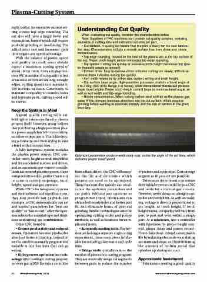
Optimized parameters produce weld-ready cuts; notice the angle of the cut lines, which indicates proper travel speed.
32 MetalForming/July 2016
www.metalformingmagazine.com
from a flash drive), the CNC will exam- ine the file and determine which parameters need to be optimized. Then the controller quickly can recal- culate the optimum parameters and cut paths. Without any operator or programmer input, fabricators can obtain bolt-ready holes and better part fit, and eliminate hours of post-cut grinding. Similar technologies exist for optimizing cutting order and pierce methods, as well as locations for com- plicated nests.
• Automatic nesting tools. For fab- ricators lacking a separate engineering department, these tools prove invalu- able for reducing plate waste and cycle time.
• Bridge tools typically reduce the number of pierces in a cutting program. They automatically assign cut segments between parts to reduce the number
of pierces and cycle time. Cost savings as great as 40 percent are possible.
Fabricators determined to minimize their initial expense could forgo a CNC and settle for a manual gas console. However, never skimp on a height con- troller and torch lifter. As with arc weld- ing, voltage is directly proportional to arc length, or torch height. If torch height varies, cut quality will vary from part to part and even within a single part. At a minimum, use a controller with functions for pierce-height con- trol, pierce delay and pierce retract. These functions extend consumable life by reducing electrode wear during arc starts and stops, and by minimizing the amount of molten metal that splashes up during arc start.
Approximate Investment
Fabricators seeking a good-quality
