
Page 47 - MetalForming May 2016
P. 47
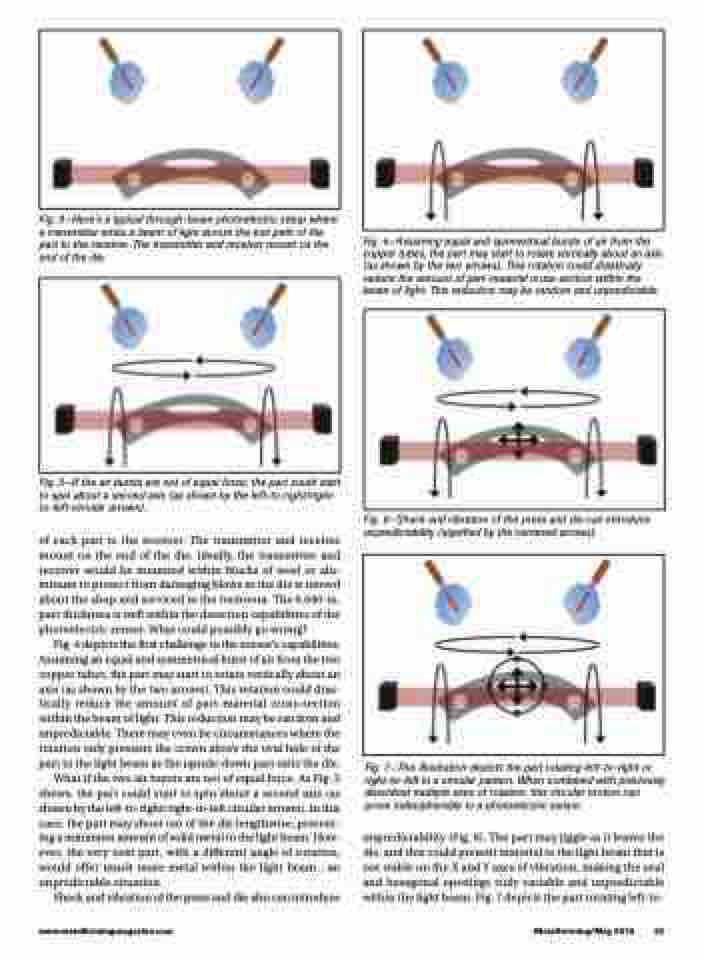
  Fig. 3—Here’s a typical through-beam photoelectric setup where a transmitter emits a beam of light across the exit path of the part to the receiver. The transmitter and receiver mount on the end of the die.
Fig. 5—If the air bursts are not of equal force, the part could start to spin about a second axis (as shown by the left-to-right/right- to-left circular arrows).
of each part to the receiver. The transmitter and receiver mount on the end of the die. Ideally, the transmitter and receiver would be mounted within blocks of steel or alu- minum to protect from damaging blows as the die is moved about the shop and serviced in the toolroom. The 0.040-in. part thickness is well within the detection capabilities of the photoelectric sensor. What could possibly go wrong?
Fig. 4 depicts the first challenge to the sensor’s capabilities. Assuming an equal and symmetrical burst of air from the two copper tubes, the part may start to rotate vertically about an axis (as shown by the two arrows). This rotation could dras- tically reduce the amount of part-material cross-section within the beam of light. This reduction may be random and unpredictable. There may even be circumstances where the rotation only presents the crown above the oval hole of the part to the light beam as the upside-down part exits the die.
What if the two air bursts are not of equal force. As Fig. 5 shows, the part could start to spin about a second axis (as shown by the left-to-right/right-to-left circular arrows). In this case, the part may shoot out of the die lengthwise, present- ing a minimum amount of solid metal to the light beam. How- ever, the very next part, with a different angle of rotation, would offer much more metal within the light beam...an unpredictable situation.
Shock and vibration of the press and die also can introduce
Fig. 4—Assuming equal and symmetrical bursts of air from the copper tubes, the part may start to rotate vertically about an axis (as shown by the two arrows). This rotation could drastically reduce the amount of part-material cross-section within the beam of light. This reduction may be random and unpredictable.
Fig. 6—Shock and vibration of the press and die can introduce unpredictability (signified by the centered arrows).
Fig. 7—This illustration depicts the part rotating left-to-right or right-to-left in a circular pattern. When combined with previously described multiple axes of rotation, this circular motion can prove indecipherable to a photoelectric sensor.
unpredictability (Fig. 6). The part may jiggle as it leaves the die, and this could present material to the light beam that is not stable on the X and Y axes of vibration, making the oval and hexagonal openings truly variable and unpredictable within the light beam. Fig. 7 depicts the part rotating left-to-
   www.metalformingmagazine.com
MetalForming/May 2016 45
