
Page 46 - MetalForming May 2016
P. 46
Understanding Sensors
& Error-Proofing, Part 2:
Failure Modes for Photoelectric
Sensors
Frustrating to many a metal stamper is the seemingly magical reaction that photoelectric sensors can have to a moving stamped part. The sensor salesperson assures you that this particular sensor will detect your stamped part—even as that part exits the die rotating and gyrating into various flight paths on its way to the container. So, the sen- sor is purchased and mounted on the die to detect the exit of the stamped part. All seems to be okay for several hours, per- haps even for a full day’s run. Then it starts...a seemingly ran- dom and intermittent series of nuisance stops. The operator checks the die and sure enough—the part did exit but some- how the sensor failed to detect it. Why would the process work for many strokes of the press and then, with no apparent change in that process, the sensor fails to detect the part?
The sensor salesperson assured a flawless application, and it sure seems that way for 99.9 percent of the time. But pro- duction floors view that 0.1-percent failure rate with disdain, and rightly so as it can translate to dozens of nuisance stops in a given day. What to do? How to simulate all possible part position on a test bench to eliminate even the slightest pos- sibility of a blind spot in a million possible exit configuration for that part? How should one test for conditions that seem impossible to predict? There is a way.
Consider Part Rotations, Orientations As they Exit Dies
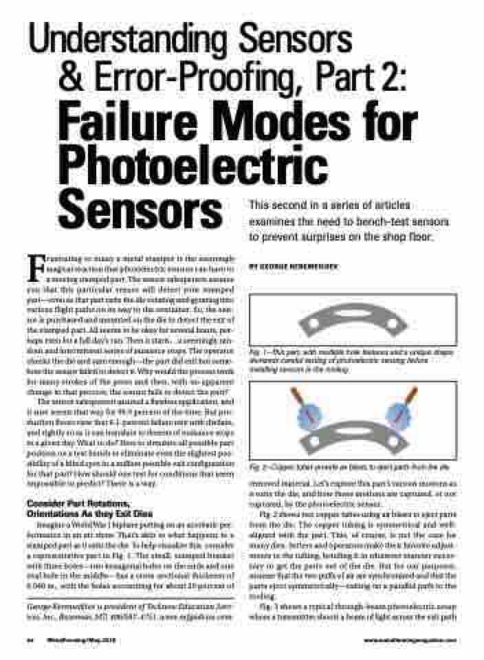
Imagine a World War I biplane putting on an acrobatic per- formance in an air show. That’s akin to what happens to a stamped part as it exits the die. To help visualize this, consider a representative part in Fig. 1. The small, stamped bracket with three holes—two hexagonal holes on the ends and one oval hole in the middle—has a cross-sectional thickness of 0.040 in., with the holes accounting for about 20 percent of
George Keremedjiev is president of Tecknow Education Serv- ices, Inc., Bozeman, MT; 406/587-4751, www.mfgadvice.com.
This second in a series of articles examines the need to bench-test sensors to prevent surprises on the shop floor.
BY GEORGE KEREMEDJIEV
Fig. 1—This part, with multiple hole features and a unique shape, demands careful testing of photoelectric sensing before installing sensors in the tooling.
Fig. 2—Copper tubes provide air blasts to eject parts from the die.
removed material. Let’s explore this part’s various motions as it exits the die, and how these motions are captured, or not captured, by the photoelectric sensor.
Fig. 2 shows two copper tubes using air blasts to eject parts from the die. The copper tubing is symmetrical and well- aligned with the part. This, of course, is not the case for many dies. Setters and operators make their favorite adjust- ments to the tubing, bending it in whatever manner neces- sary to get the parts out of the die. But for our purposes, assume that the two puffs of air are synchronized and that the parts eject symmetrically—exiting on a parallel path to the tooling.
Fig. 3 shows a typical through-beam photoelectric setup where a transmitter shoots a beam of light across the exit path
44 MetalForming/May 2016
www.metalformingmagazine.com
