
Page 40 - MetalForming March 2015
P. 40
The Science of Forming
By Stuart Keeler
Forming-Limit Curves Becoming More Important
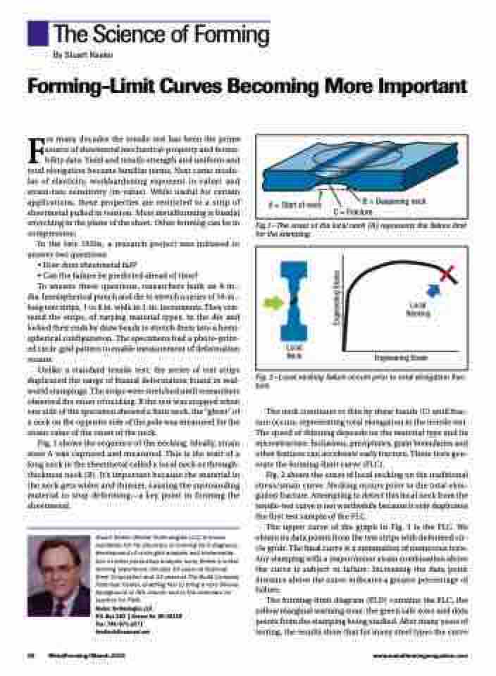
A = Start of neck
B = Deepening neck C = Fracture
For many decades the tensile test has been the prime source of sheetmetal mechanical-property and forma- bility data. Yield and tensile strength and uniform and total elongation became familiar terms. Next came modu- lus of elasticity, workhardening exponent (n-value) and strain-rate sensitivity (m-value). While useful for certain applications, these properties are restricted to a strip of sheetmetal pulled in tension. Most metalforming is biaxial stretching in the plane of the sheet. Other forming can be in compression.
In the late 1950s, a research project was initiated to answer two questions:
• How does sheetmetal fail?
• Can the failure be predicted ahead of time?
To answer these questions, researchers built an 8-in.-
dia. hemispherical punch and die to stretch a series of 10-in.- long test strips, 1 to 8 in. wide in 1-in. increments. They cen- tered the strips, of varying material types, in the die and locked their ends by draw beads to stretch them into a hemi- spherical configuration. The specimens had a photo-print- ed circle-grid pattern to enable measurement of deformation strains.
Unlike a standard tensile test, the series of test strips duplicated the range of biaxial deformation found in real- world stampings. The strips were stretched until researchers observed the onset of necking. If the test was stopped when one side of the specimen showed a faint neck, the “ghost” of a neck on the opposite side of the pole was measured for the strain value of the onset of the neck.
Fig. 1 shows the sequence of the necking. Ideally, strain state A was captured and measured. This is the start of a long neck in the sheetmetal called a local neck or through- thickness neck (B). It’s important because the material in the neck gets wider and thinner, causing the surrounding material to stop deforming—a key point in forming the sheetmetal.
Stuart Keeler (Keeler Technologies LLC) is known worldwide for his discovery of forming limit diagrams, development of circle-grid analysis and implementa- tion of other press-shop analysis tools. Keeler’s metal- forming experience includes 24 years at National Steel Corporation and 12 years at The Budd Company Technical Center, enabling him to bring a very diverse background to this column and to the seminars he teaches for PMA.
Keeler Technologies LLC
P.O. Box 283 | Grosse Ile, MI 48138 Fax: 734/671-2271 keeltech@comcast.net
Fig.1—The onset of the local neck (A) represents the failure limit for the stamping.
Local Neck
Local Necking
Engineering Strain
Fig. 2—Local necking failure occurs prior to total elongation frac- ture.
The neck continues to thin by shear bands (C) until frac- ture occurs, representing total elongation in the tensile test. The speed of thinning depends on the material type and its microstructure. Inclusions, precipitates, grain boundaries and other features can accelerate early fracture. These tests gen- erate the forming-limit curve (FLC).
Fig. 2 shows the onset of local necking on the traditional stress/strain curve. Necking occurs prior to the total elon- gation fracture. Attempting to detect this local neck from the tensile-test curve is not worthwhile because it only duplicates the first test sample of the FLC.
The upper curve of the graph in Fig. 3 is the FLC. We obtain its data points from the test strips with deformed cir- cle grids. The final curve is a summation of numerous tests. Any stamping with a major/minor strain combination above the curve is subject to failure. Increasing the data point distance above the curve indicates a greater percentage of failure.
The forming-limit diagram (FLD) contains the FLC, the yellow marginal warning zone, the green safe zone and data points from the stamping being studied. After many years of testing, the results show that for many steel types the curve
38 MetalForming/March 2015
www.metalformingmagazine.com
Engineering Stress
