
Page 41 - MetalForming March 2015
P. 41
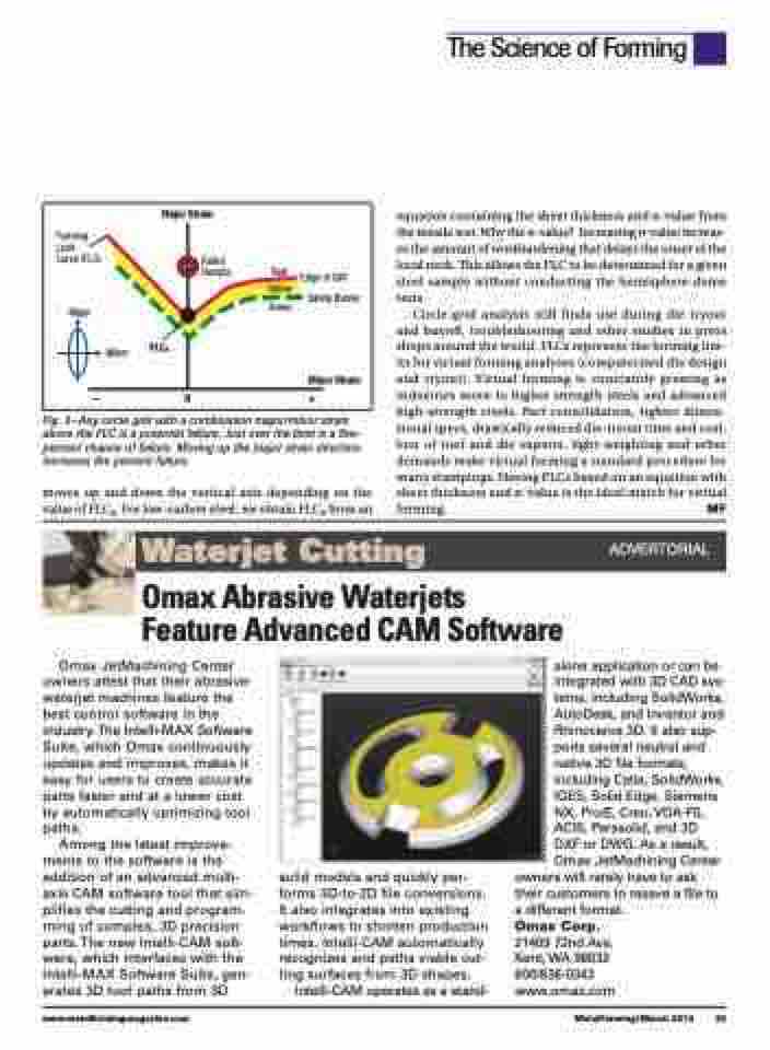
  Fig. 3—Any circle grid with a combination major/minor strain above the FLC is a potential failure. Just over the limit is a five- percent chance of failure. Moving up the major strain direction increases the percent failure.
moves up and down the vertical axis depending on the value of FLC0. For low-carbon steel, we obtain FLC0 from an
equation containing the sheet thickness and n-value from the tensile test. Why the n-value? Increasing n-value increas- es the amount of workhardening that delays the onset of the local neck. This allows the FLC to be determined for a given steel sample without conducting the hemisphere-dome tests.
Circle-grid analysis still finds use during die tryout and buyoff, troubleshooting and other studies in press shops around the world. FLCs represent the forming lim- its for virtual forming analyses (computerized die design and tryout). Virtual forming is constantly growing as industries move to higher strength steels and advanced high-strength steels. Part consolidation, tighter dimen- sional specs, drastically reduced die-tryout time and cost, loss of tool and die experts, light-weighting and other demands make virtual forming a standard procedure for many stampings. Having FLCs based on an equation with sheet thickness and n-value is the ideal match for virtual forming. MF
The Science of Forming
  Forming Limit
Curve (FLC)
Major
Red Edge of Cliff
Major Strain
Failed Sample
FLC0
–0+
 Yellow
Green
Safety Barrier
  Minor
Minor Strain
   Waterjet Cutting
ADVERTORIAL
Omax Abrasive Waterjets Feature Advanced CAM Software
 Omax JetMachining Center owners attest that their abrasive- waterjet machines feature the best control software in the industry.The Intelli-MAX Software Suite, which Omax continuously updates and improves, makes it easy for users to create accurate parts faster and at a lower cost by automatically optimizing tool paths.
Among the latest improve- ments to the software is the addition of an advanced multi- axis CAM software tool that sim- plifies the cutting and program- ming of complex, 3D precision parts.The new Intelli-CAM soft- ware, which interfaces with the Intelli-MAX Software Suite, gen- erates 3D tool paths from 3D
solid models and quickly per- forms 3D-to-2D file conversions. It also integrates into existing workflows to shorten production times. Intelli-CAM automatically recognizes and paths viable cut- ting surfaces from 3D shapes.
Intelli-CAM operates as a stand-
alone application or can be integrated with 3D CAD sys- tems, including SolidWorks, AutoDesk, and Inventor and Rhinoceros 3D. It also sup- ports several neutral and native 3D file formats, including Catia, SolidWorks, IGES, Solid Edge, Siemens NX, Pro/E, Creo, VDA-FS, ACIS, Parasolid, and 3D DXF or DWG. As a result, Omax JetMachining Center
owners will rarely have to ask their customers to resave a file to a different format.
Omax Corp.
21409 72nd Ave.
Kent, WA 98032
800/838-0343
www.omax.com
 www.metalformingmagazine.com
MetalForming/March 2015 39
