
Page 22 - MetalForming March 2015
P. 22
Motion Controllers
between the end of the plate and the center hole to be punched. Two cen- tering jaws along the width of the plate activate to center the hole accurately along that width. The pusher and end- gauge axes travel via position control, while the centering jaws use position and force control. One jaw moves to a target position and the other jaw uses force control to clamp the part.
“The ability to combine different types of axis control in one system was very helpful,” says Greg Shortridge, Dayton Parts electrical engineer. “Using position and force control, we can ensure that the parts are securely held, at the same time avoiding the risk of damage due to clamping them too tightly.
“And we had never used force con- trol before,” he adds. “But performing pressure/force control was simple using the Delta controllers.”
The last two of the six axes operate the punch, a 10-in.-bore hydraulic cylinder operated by a servo-hydraulic valve, and stripper.
Magnetostrictive displacement trans- ducers provide position feedback for the hydraulic cylinders that operate the punch, stripper and centering jaws, while the end gauge is positioned via a servo motor with absolute encoder to provide position feedback. The pusher, operated by a hydraulic cylinder, also uses an absolute encoder indicating position.
“The new controllers give us very accurate positioning,” says Shortridge. “Every axis can be positioned to with- in 0.001 in.”
The forming head is operated by two motion axes, one to clamp the part in the frame for bending (Fig. 3) to its desired shape, and the other to move the frame vertically. The clamp uses automatic pressure control when it engages, ensuring that the part clamps to a specific pressure in the form that establishes the appropriate bend to the leaf spring. This is accomplished via a PLC and automatic pressure regulator in conjunction with a proportional valve. When clamping the part, pressure is controlled via the regulator. When unclamping, an RMC75 two-axis elec-
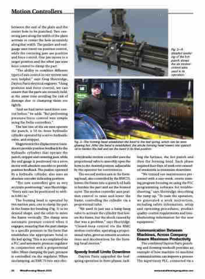
Fig. 2—A detailed render- ing of the hot punch shows the six motion- control axes used in its operation.
Fig. 3—The forming head establishes the bend in the leaf spring, which can be seen glowing hot. After the bend is established, the whole forming head lowers into quench oil to harden the leaf and set the bend in its final position.
20 MetalForming/March 2015
www.metalformingmagazine.com
trohydraulic motion controller uses the proportional valve to smoothly open the form to the desired positon, adjustable by the operator for convenience.
The second motion axis in the form- ing head, also controlled by the RMC75, lowers the frame into a quench oil bath to harden the part and set the formed curve. The motion controller uses posi- tion control to raise and lower the frame, controlling the cylinder via a proportional valve.
“We used to just use a bang-bang valve to activate the cylinder that low- ers the frame, but the shock caused by that was a problem,” says Shortridge. “Closed-loop control via the RMC motion controller, operating a propor- tional valve, gives us smooth accelera- tions and decelerations for the form- ing-head motion.”
Speedy Install Limits Downtime
Dayton Parts upgraded the leaf- spring operation in three phases, tack-
ling the furnace, the hot punch and then the forming head. Each phase required four days of work over extend- ed weekends to minimize downtime.
“We trained our maintenance per- sonnel with a one-week, onsite train- ing program focusing on using the PLC programming software for trouble- shooting,” says Shortridge, describing the ramp up. “To train the operators, we generated a work instruction, including safety information, setup and operating procedures, product quality-control requirements and trou- bleshooting information for the new equipment.”
Communication Between Machines, Across Company Ensure Maximum Productivity
The combined Dayton Parts punch- ing and forming workcell provides an example of how machine-to-machine communications can improve a process. The supervisory PLC, connected via a
