
Page 41 - MetalForming February 2015
P. 41
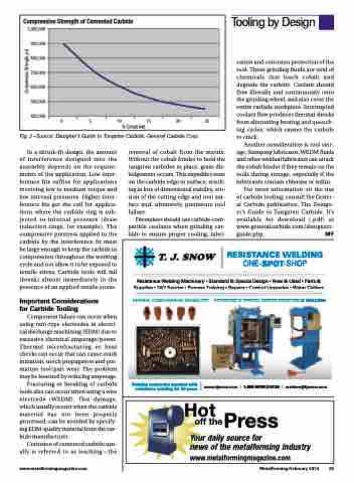
                  Compressive Strength of Cemented Carbide
1,000,000 900,000 800,000 700,000 600,000 500,000 400,000
              0 5 10 15 20 25 % Cobalt (wt)
  Fig. 2—Source: Designer’s Guide to Tungsten Carbide, General Carbide Corp.
cation and corrosion protection of the tool. These grinding fluids are void of chemicals that leach cobalt and degrade the carbide. Coolant should flow liberally and continuously onto the grinding wheel, and also cover the entire carbide workpiece. Interrupted coolant flow produces thermal shocks from alternating heating and quench- ing cycles, which causes the carbide to crack.
Another consideration is tool stor- age. Stamping lubricants, WEDM fluids and other residual lubricants can attack the cobalt binder if they remain on the tools during storage, especially if the lubricants contain chlorine or sulfur.
For more information on the use of carbide tooling, consult the Gener- al Carbide publication, The Design- er’s Guide to Tungsten Carbide. It’s available for download (.pdf ) at www.generalcarbide.com/designers- guide.php. MF
RESISTANCE WELDING ONE-SPOT-SHOP
In a shrink-fit design, the amount of interference designed into the assembly depends on the require- ments of the application. Low inter- ference fits suffice for applications involving low to medium torque and low internal pressures. Higher inter- ference fits get the call for applica- tions where the carbide ring is sub- jected to internal pressure (draw reduction rings, for example). The compressive prestress applied to the carbide by the interference fit must be large enough to keep the carbide in compression throughout the working cycle and not allow it to be exposed to tensile stress. Carbide tools will fail (break) almost immediately in the presence of an applied tensile stress.
Important Considerations for Carbide Tooling
Component failure can occur when using ram-type electrodes in electri- cal discharge machining (EDM) due to excessive electrical amperage/power. Thermal microfracturing or heat checks can occur that can cause crack initiation, notch propagation and pre- mature tool/part wear. The problem may be lessened by reducing amperage.
Fracturing or breaking of carbide tools also can occur when using a wire electrode (WEDM). This damage, which usually occurs when the carbide material has not been properly processed, can be avoided by specify- ing EDM-quality material from the car- bide manufacturer.
Corrosion of cemented carbide usu- ally is referred to as leaching—the
removal of cobalt from the matrix. Without the cobalt binder to hold the tungsten carbides in place, grain dis- lodgement occurs. This expedites wear on the carbide edge or surface, result- ing in loss of dimensional stability, ero- sion of the cutting edge and tool sur- face and, ultimately, premature tool failure.
Diemakers should use carbide-com- patible coolants when grinding car- bide to ensure proper cooling, lubri-
ne
er
ry
y•
•S
St
ta
an
nd
da
ar
rd
d&
Tooling by Design
                          & Supplies • 24/7 Service • Process Training • Repairs • Control Upgrades • Water Chillers
Resistance Welding M
Ma
ac
ch
hi
in
&S
Sp
pe
ec
ci
ia
al
lD
De
es
s
si
ig
gn
n •
• N
Ne
ew
w &
& U
Us
se
ed
d •
• P
Pa
ar
rt
ts
s &
                      DIVERSE CONSUMABLES INVENTORY
STANDARD & SPECIAL DESIGN RESISTANCE WELDERS
                                                off the
Hot Press
Your daily source for
news of the metalforming industry www.metalformingmagazine.com
  www.metalformingmagazine.com
MetalForming/February 2015 39
Helping customers succeed with resistance welding for 50 years
www.tjsnow.com | 1-800-NOW-SNOW | welders@tjsnow.com
 Compressive Strength, psi
