
Page 27 - MetalForming November 2014
P. 27
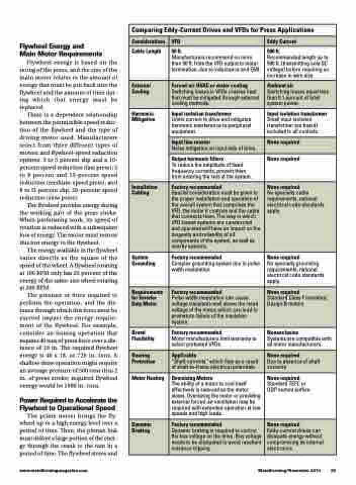
    Comparing Eddy-Current Drives and VFDs for Press Applications
 Considerations
VFD
Eddy Current
Cable Length
50 ft.
Manufacturers recommend no more than 50 ft. from the VFD output to motor termination, due to inductance and EMI.
500 ft.
Recommended length up to 500 ft. (transmitting only DC voltage) before requiring an increase in wire size.
External Cooling
Forced-air HVAC or water cooling
Switching losses in VFDs creates heat that must be mitigated through external cooling methods.
Ambient air
Switching losses equal less than 0.1 percent of total system power.
 Harmonic Mitigation
Input isolation transformer
Limits current to drive and mitigates harmonic interference to peripheral equipment.
Input isolation transformer
Small input isolation transformer (on board) included in all controls.
Input line reactor
Noise mitigation on input side of drive.
None required
Output harmonic filters
To reduce the amplitude of fixed frequency currents, prevent them from entering the rest of the system.
None required
Installation Cabling
Factory recommended
Special consideration must be given to the proper installation and operation of the overall system that comprises the VFD, the motor it controls and the cable that connects them. The way in which VFD-based systems are constructed and operated will have an impact on the longevity and reliability of all components of the system, as well as nearby systems.
None required
No specialty cable requirements, national electrical code standards apply.
System Grounding
Factory recommended
Complex grounding system due to pulse width modulation
None required
No specialty grounding requirements, national electrical code standards apply.
Requirements for Inverter Duty Motor
Factory recommended
Pulse-width modulation can cause voltage transients well above the rated voltage of the motor, which can lead to premature failure of the insulation system.
None required
Standard Class F insulated, Design B motors
Brand Flexibility
Factory recommended
Motor manufacturers limit warranty to select pretested VFDs.
Nonexclusive
Systems are compatible with all motor manufacturers.
Bearing Protection
Applicable
“Shaft currents” which flow as a result of shaft-to-frame electrical potentials.
None required
Due to absence of shaft currents
Motor Heating
Oversizing Motors
The ability of a motor to cool itself effectively is reduced as the motor slows. Oversizing the motor or providing external forced-air ventilation may be required with extended operation at low speeds and high loads.
None required
Standard TEFC or ODP motors suffice
Dynamic Braking
Factory recommended
Dynamic braking is required to control the bus voltage on the drive. Bus voltage needs to be dissipated to avoid resultant nuisance tripping.
None required
Eddy-current drives can dissipate energy without compromising its internal electronics.
   Flywheel Energy and
Main Motor Requirements
Flywheel energy is based on the rating of the press, and the size of the main motor relates to the amount of energy that must be put back into the flywheel and the amount of time dur- ing which that energy must be replaced.
There is a dependent relationship between the permissible speed reduc- tion of the flywheel and the type of driving motor used. Manufacturers select from three different types of motors and flywheel-speed reduction options: 3 to 5 percent slip and a 10- percent speed reduction (fast press); 5 to 8 percent and 15-percent speed reduction (medium-speed press); and 8 to l3 percent slip, 20-percent speed reduction (slow press).
The flywheel provides energy during the working part of the press stroke. When performing work, its speed of rotation is reduced with a subsequent loss of energy. The motor must restore this lost energy to the flywheel.
The energy available in the flywheel varies directly as the square of the speed of the wheel. A flywheel rotating at 100 RPM only has 25 percent of the energy of the same-size wheel rotating at 200 RPM.
The pressure or force required to perform the operation, and the dis- tance through which this force must be exerted impact the energy require- ment of the flywheel. For example, consider an ironing operation that requires 40 tons of press force over a dis- tance of 18 in. The required flywheel energy is 40 x 18, or 720 in.-tons. A shallow draw operation might require an average pressure of 500 tons thru 2 in. of press stroke; required flywheel energy would be 1000 in.-tons.
Power Required to Accelerate the Flywheel to Operational Speed
The prime mover brings the fly- wheel up to a high energy level over a period of time. Then, the pitman link must deliver a large portion of the ener- gy through the crank to the ram in a period of time. The flywheel stores and
                         www.metalformingmagazine.com
MetalForming/November 2014 25
