
Page 48 - MetalForming March 2014
P. 48
The Science of Forming
By Stuart Keeler
Track and Eliminate Rogue Forces
3 22
33
2 131
1
1
2
Stampings are becoming more complex. In one die, stampers can make parts that once comprised three sep- arate stampings. Also, weight-reduction programs demand thinner-gauge parts with higher strengths, and dimensional specifications have tightened. All the while, lead time from order to delivery has been slashed. When nec- essary, troubleshooting must be quick, accurate and incor- porate new concepts.
A friend who owns a medical clinic stopped me in his wait- ing room one day to describe a frustrating problem. The ceil- ing of the waiting room leaked water every time it rained. Removing several ceiling tiles, he found water dripping from a steel I-beam and applied several gallons of sealant on top of the roof at that location, with no success.
My immediate advice: “If your roof leaks, think like water not like a roof. The roof only becomes a problem when an outside force (the water) interferes with status quo. Track the water and you’ll find the solution.”
Examining the beam revealed water all along its length, due to its downward slope from the far end of the waiting room to the location of the leak. Removing tiles from the opposite end of the beam revealed a crack in the roof struc- ture—the source of the problem.
This concept applies to press-shop troubleshooting. If a stamping fails, think like force not like a stamping. Like the roof, the stamping only becomes a problem when outside forces interfere and alter the forming process. The amount of force divided by the crosssectional contact area becomes a stress that causes deformation (strain). Control and apply the force properly and the stamping will form according to print. Troubleshooters must track down and correct any unexpected rogue forces.
Three case studies will help illustrate this troubleshooting approach. The first: a symmetrical elliptical stamping with sidewall tearing always located toward the operator. Check- ing the stamping die dimensionally confirmed that both halves exhibited symmetry, and inspecting the blank failed
Stuart Keeler (Keeler Technologies LLC) is known worldwide for his discovery of forming limit diagrams, development of circle-grid analysis and implementa- tion of other press-shop analysis tools. Keeler’s metal- forming experience includes 24 years at National Steel Corporation and 12 years at The Budd Company Technical Center, enabling him to bring a very diverse background to this column and to the seminars he teaches for PMA.
Keeler Technologies LLC
P.O. Box 283 | Grosse Ile, MI 48138 Fax: 734/671-2271 keeltech@comcast.net
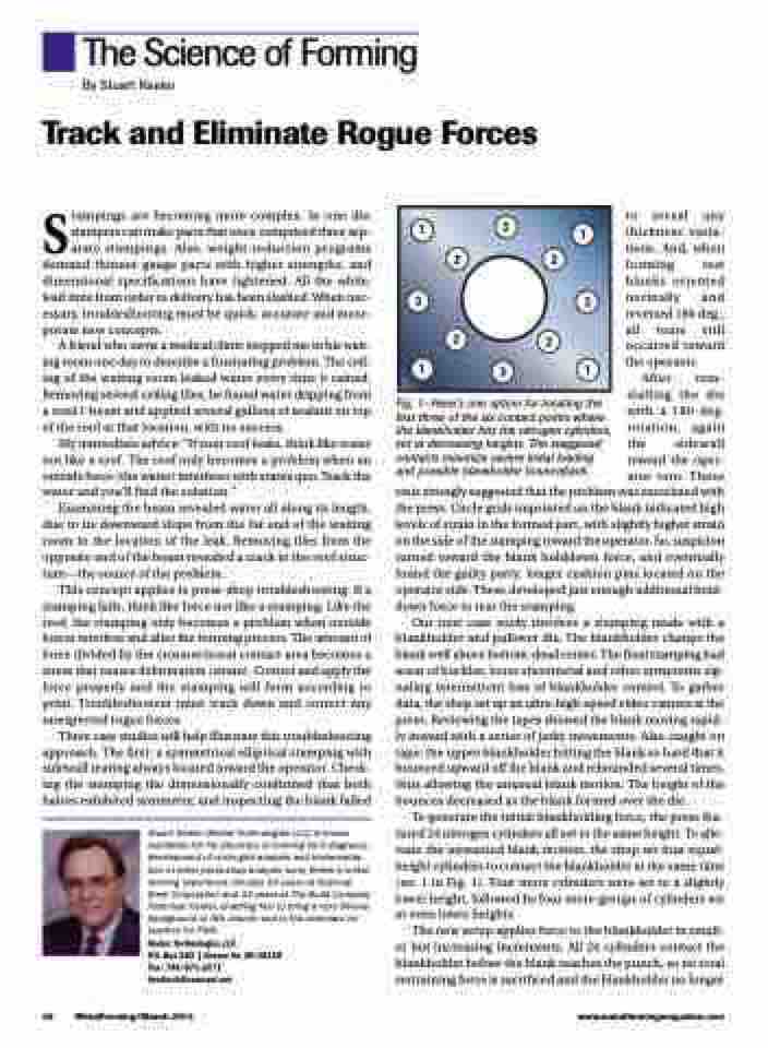
Fig. 1—Here’s one option for locating the first three of the six contact points where the blankholder hits the nitrogen cylinders, set at decreasing heights. The staggered contacts minimize severe initial loading and possible blankholder bounceback.
to reveal any thickness varia- tions. And, when forming test blanks oriented normally and reversed 180 deg., all tears still occurred toward the operator.
After rein- stalling the die with a 180-deg. rotation, again the sidewall toward the oper- ator tore. These
tests strongly suggested that the problem was associated with the press. Circle grids imprinted on the blank indicated high levels of strain in the formed part, with slightly higher strain on the side of the stamping toward the operator. So, suspicion turned toward the blank holddown force, and eventually found the guilty party: longer cushion pins located on the operator side. These developed just enough additional hold- down force to tear the stamping.
Our next case study involves a stamping made with a blankholder and pullover die. The blankholder clamps the blank well above bottom-dead center. The final stamping had areas of buckles, loose sheetmetal and other symptoms sig- naling intermittent loss of blankholder control. To gather data, the shop set up an ultra-high-speed video camera at the press. Reviewing the tapes showed the blank moving rapid- ly inward with a series of jerky movements. Also caught on tape: the upper blankholder hitting the blank so hard that it bounced upward off the blank and rebounded several times, thus allowing the unusual blank motion. The height of the bounces decreased as the blank formed over the die.
To generate the initial blankholding force, the press fea- tured 24 nitrogen cylinders all set to the same height. To alle- viate the unwanted blank motion, the shop set four equal- height cylinders to contact the blankholder at the same time (no. 1 in Fig. 1). Four more cylinders were set to a slightly lower height, followed by four more groups of cylinders set at even lower heights.
The new setup applies force to the blankholder in small- er but increasing increments. All 24 cylinders contact the blankholder before the blank reaches the punch, so no total restraining force is sacrificed and the blankholder no longer
46 MetalForming/March 2014
www.metalformingmagazine.com
