
Page 28 - MetalForming February 2014
P. 28
resumes after only a few minutes.
To further facilitate changeout, the ideal weld-tool setup includes quick disconnects on air and electrical lines, as well as plug-and-play communica- tions components. These setups can make quick work of large weld tools, too, with automated systems to carry the behemoths in and out of the weld cell, and a positioner to hydraulically
clamp the tool in place.
Even though parts must meet cer-
tain tolerances, some unexpected vari- ation occurs, especially when a user welds parts that arrive from different suppliers. To assist in changeout and production in these instances, tooling may be shimmable in positions along x, y and z axes. Allowing users to slight- ly shim the fixtures accounts for part variation and enables rapid return to production.
Staging of fixtures and changeout tooling assists in quick-change oper- ations, as well. To maintain production levels, metalformers should stage parts as closely as possible to the weld tools. A well-designed process allows parts to be brought in on carts that integrate with the safety zone of the weld cell. And, following the welding process, oftentimes cell operators will remove the assemblies and place them on racks.
To prevent operators from becoming bottlenecks in the process, systems increasingly implement robots to han- dle completed welded assemblies. A robot with a gripper may come in and pull the final assembly out of the fixture from the back, as the operator prepares the next assembly in the front of the weld cell. The robot takes care of removal and may even perform addi- tional operations on the assembly before depositing it on a conveyor.
Fixturing Evolves to Handle Increased Complexity, and Laser Welding
Automotive seat frames provide a vivid illustration of how welded assem- blies have become increasingly com- plex. Only 20 years ago, most seat frames consisted of a bulky outer frame
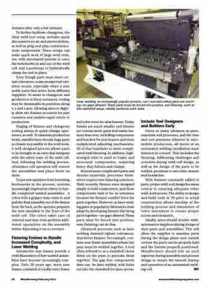
Laser welding, an increasingly popular process, can’t succeed unless parts are touch- ing—no gaps allowed. These parts must be forced into position, and fixturing, such as this clamshell setup, reliably performs such tasks.
26 MetalForming/February 2014
www.metalformingmagazine.com
and a few wires for attachments. Today, frames are much smaller and thinner yet contain more parts and safety fea- tures than ever, including components and brackets for seat heaters and more complicated adjusting mechanisms. All of that translates to more compli- cated weld fixturing. In addition, high- strength steel is used in frame and structural components, requiring heavy-duty fixtures and clamps.
Beyond more complicated parts and thinner materials, processes them- selves require new fixturing solutions. Until recently, fixtures were designed simply to hold components, and those components had to be in-tolerance because the fixtures couldn’t force the parts together. However, as laser weld- ing gains in popularity, fabricators must adapt by developing fixtures that bring parts together—no gaps allowed. These parts must be forced into position; now, fixturing can do that.
Advanced processes such as laser welding demand tighter tolerances, thus better fixtures. For example, con- sider sear-frame assemblies where two pans must be welded together. A tool often referred to as a clamshell closes down on the pans to pancake them together. The gap-free components then can be laser welded, with holes cut into the clamshell for laser access.
Include Tool Designers and Builders Early
Given so many advances in parts, materials and processes, and the time and cost pressures inherent in auto- mobile production, all facets of an automated-welding installation must function in concert. That includes the fixturing. Addressing challenges and concerns during weld-cell design, as well as the design of the parts to be welded, promises to save time, money and headaches.
With features constantly added to parts, proper weld-tool design becomes critical to ensuring adequate robot weld-joint access. The ability to design and build tools in 3D prior to actual construction allows mockup of the welding process and simulation of robot movement to ensure proper access and clearance.
Ideally, users should involve weld- automation suppliers during design of their parts and assemblies. This will allow the supplier to examine parts during the design phase and consult on how the parts can be properly held and the fixtures properly positioned. Metalformers should rely on such expertise during assembly and process design to ensure the smooth startup and operation of an automated-weld- ing cell. MF
