
Page 27 - MetalForming February 2014
P. 27
will allow a part to practically fall into its proper location and orientation by itself. An end-user typically wants its employees simply to load a fixture, and not have to take the extra steps to ensure proper orientation. That’s the job of the fixture.
Best practices:
• The operator simply drops the part into the fixture and everything locates correctly;
• The parts are clamped and welded; and
• The welded assembly discharges. Ultimately, the system welds the assembly correctly every time.
Guard Against Spatter
The most common failure points on weld tools are sensors, sensor cables and air lines. Failures to these compo- nents affect location accuracy. Weld spatter is a major culprit, so a well- designed fixturing system must include measures to address spatter.
Best-practice systems feature a Teflon-based coating that resists spat- ter. These coatings can last as long as two years, depending on how well the fixtures are maintained. With the prop- er coating, spatter lays on top of the tooling rather than sticking to it. In addition to the coating, fixture builders will machine some fixture components from hardened materials, to repel heat and spatter.
Besides protecting the weld tools, users obviously seek to protect their parts from spatter. This can be accom- plished via coated spatter covers placed on the ends of clamps. As the clamps close, the covers protect the areas of the assembly most susceptible to spat- ter. After welding, the covers retract. Other shields, some permanent, may be placed to protect fixture compo- nents and parts.
Proper fixturing also protects part features that require additional oper- ations after welding, such as mounting surfaces, fasteners and bolt holes. Here, toggle or rotary clamps find use to cover at-risk features.
PLCs incorporated into fixturing enable simple control of clamps, slides
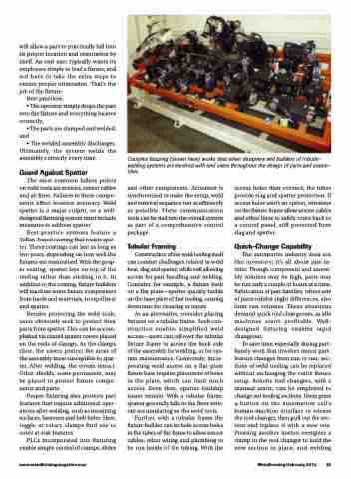
Complex fixturing (shown here) works best when designers and builders of robotic- welding systems are involved with end users throughout the design of parts and assem- blies.
www.metalformingmagazine.com
MetalForming/February 2014 25
and other components. Actuation is synchronized to make the setup, weld and removal sequence run as efficiently as possible. These communication tools can be tied into the overall system as part of a comprehensive control package.
Tubular Framing
Construction of the weld tooling itself can combat challenges related to weld heat, slag and spatter, while still allowing access for part handling and welding. Consider, for example, a fixture built on a flat plate—spatter quickly builds on the base plate of that tooling, causing downtime for cleaning or repair.
As an alternative, consider placing fixtures on a tubular frame. Such con- struction enables simplified weld access—users can roll over the tubular fixture frame to access the back side of the assembly for welding, or for sys- tem maintenance. Conversely, incor- porating weld access on a flat-plate fixture base requires placement of holes in the plate, which can limit torch access. Even then, spatter-buildup issues remain. With a tubular frame, spatter generally falls to the floor with- out accumulating on the weld tools.
Further, with a tubular frame the fixture builder can include access holes in the tubes of the frame to allow sensor cables, other wiring and plumbing to be run inside of the tubing. With the
access holes then covered, the tubes provide slag and spatter protection. If access holes aren’t an option, wireways on the fixture frame allow sensor cables and other lines to safely route back to a control panel, still protected from slag and spatter.
Quick-Change Capability
The automotive industry does not like inventory; it’s all about just-in- time. Though component and assem- bly volumes may be high, parts may be run only a couple of hours at a time. Fabrication of part families, where sets of parts exhibit slight differences, also limit run volumes. These situations demand quick tool changeouts, as idle machines aren’t profitable. Well- designed fixturing enables rapid changeout.
To save time, especially during part- family work that involves minor part- feature changes from run to run, sec- tions of weld tooling can be replaced without exchanging the entire fixture setup. Robotic tool changers, with a manual assist, can be employed to change out tooling sections. Users press a button on the automation cell’s human-machine interface to release the tool changer, then pull out the sec- tion and replace it with a new one. Pressing another button energizes a clamp in the tool changer to hold the new section in place, and welding
