
Page 73 - MetalForming October 2013
P. 73
The Science of Forming
Flap bends down
L
C
B
A1 Q1
P
Q
M1 A D1
M
D
by changing die and punch radii, blank size and lubrication would not be effec- tive; changes to the geometry of the stamping are required. Unfortunately the die already is in production and dimensional changes are not allowed.
One option to eliminate tears is to change the workpiece-material prop- erties. Fortunately, three different lots of steel had been used for production (see the accompanying table). The breakage rates were 100 percent, 50 percent, and 0 percent. Stretchability of a tensile-test sample depends on the workhardening capability of the sheet- metal. Increased stretchability is sig- naled by increased values of the TS/YS ratio, n-value and total elongation. The highest values of these properties belong to the steel lot having zero breakage.
Rockwell hardness is an excellent
Fig. 3—The greatest strain in the critical section is oriented along direction AC, as shown by the circle-grid ellipses. Failure (white line) is oriented approximately 45 deg. to direction of greatest strain.
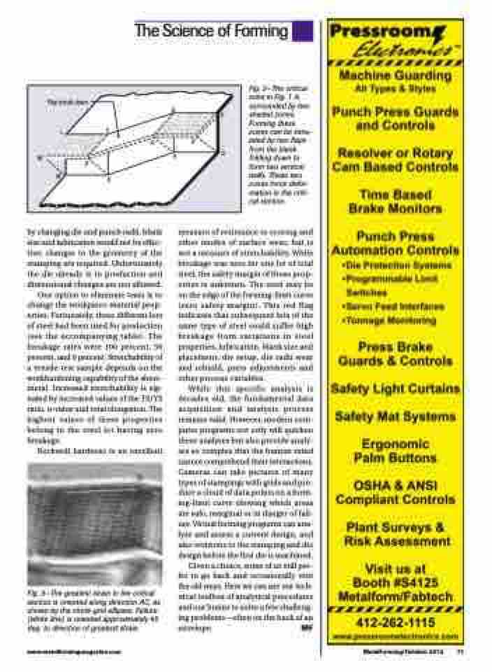
Fig. 2—The critical zone in Fig. 1 is surrounded by two shaded zones. Forming these zones can be simu- lated by two flaps from the blank folding down to form two vertical walls. These two zones force defor- mation in the criti- cal section.
measure of resistance to scoring and other modes of surface wear, but is not a measure of stretchability. While breakage was zero for one lot of trial steel, the safety margin of those prop- erties is unknown. The steel may be on the edge of the forming-limit curve (zero safety margin). This red flag indicates that subsequent lots of the same type of steel could suffer high breakage from variations in steel properties, lubrication, blank size and placement, die setup, die radii wear and rebuild, press adjustments and other process variables.
While this specific analysis is decades old, the fundamental data acquisition and analysis process remains valid. However, modern com- puter programs not only will quicken these analyses but also provide analy- ses so complex that the human mind cannot comprehend their interactions. Cameras can take pictures of many types of stampings with grids and pro- duce a cloud of data points on a form- ing-limit curve showing which areas are safe, marginal or in danger of fail- ure. Virtual forming programs can ana- lyze and assess a current design, and also revisions to the stamping and die design before the first die is machined.
Given a choice, some of us still pre- fer to go back and occasionally visit the old ways. Here we can use our tech- nical toolbox of analytical procedures and our brains to solve a few challeng- ing problems—often on the back of an envelope. MF
www.metalformingmagazine.com
MetalForming/October 2013 71
