
Page 22 - MetalForming September 2013
P. 22
Transfer Line
tion equipment (supplied by AP&T) landed at the GLMS plant in July 2012. Featured are nine Seyi mechanical press- es—a 275-ton lead press followed by eight 220-ton presses. All sit at the same die height to allow the AP&T walking- beam transfer system (two Monobar 80 units, and an AP&T Shuttle) to eas- ily index stampings down the line. The equipment sits in a new 15,000-sq.-ft. addition on the back of the plant.
Presses Called to Action, As Needed
The three brake-booster stampings comprise a front and rear cover, of 0.029-in.-thick low-carbon steel, that sandwich an 0.045-in.-thick diaphragm plate, also of low-carbon steel. Materi- al feeds from 15,000-lb. coils of stock 13 to 16 in. wide. The front cover requires five dies, run in the first five of the nine presses in the lineup. Stamping the diaphragm requires the first seven presses in the line, while stamping the rear cover requires the full nine-press lineup. Here’s where the line’s design and the flexibility it affords really pays off. Says agent Mike Gruber (who helped Hettig and his team develop the automated press line), of local industrial sales group Variegate Inc., Huntsville, AL:
“For the past decade it has been common to see four or five C-frame presses in Japanese and Korean plants in the United States lined up in a row with a transfer passing parts between them. Great Lakes Metal Stamping took this idea to the next level, to minimize its overall project cost and be much more flexible than had they invested in a large transfer press. With the two transfers and shuttle, they can run the line as a nine-press transfer or any combination less than nine. It can run as two separate transfers (five-press and four-press) or as a five-press trans- fer with four hand-fed presses.”
The shuttle mentioned by Gruber is an AP&T automation device that sits between presses five and six; the Mono- bar units link presses one through five, and six through nine. An exit conveyor rides on casters to easily move from
the end of the line to between presses five and six. Monobar 80 specs, per AP&T: 39-in. x-axis travel and 8-in. z- axis travel, with a maximum weight capacity of 176 lb. The units mount directly to each press frame.
Complete transfer-line control rests on the shoulders of a Siemens control; cam switches on each press control trig- ger on-off pulses of lubrication nozzles plumbed sporadically throughout the line, depending on the die arrangement. Each press boasts a Wintriss tonnage monitor. Sensors on the transfer mech- anisms look for verification of part pres- ence and vacuum pressure; light cur- tains guard the front side of the complete 105-ft.-long line.
A Truly Globally Sourced Project
The press line runs at 16 strokes/min. to supply Mando with 10,000 of each of the three stamped parts weekly. That has GLMS changing out the line every 1.5 days, “a 90-min. process that includes changing out the Monobar transfer racks (equipped with vacu- um-cup grippers),” explains GLMS general manager Joe Sikes, “and chang- ing out the dies.” Die store on nearby racks and move quickly onto and off the presses via rollers and locating pins on
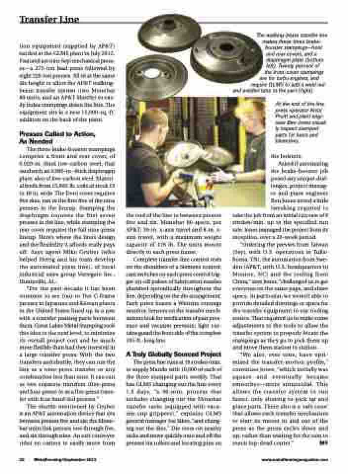
The walking-beam transfer line makes these three brake- booster stampings—front
and rear covers, and a diaphragm plate (bottom left). Twenty percent of
the front-cover stampings are for turbo engines, and
require GLMS to add a weld nut and welded tube to the part (right).
At the end of the line, press operator Kristi Pruitt and plant engi- neer Ben Jones visual- ly inspect stamped parts for burrs and blemishes.
the bolsters.
Asked if automating
the brake-booster job posed any unique chal- lenges, project manag- er and plant engineer Ben Jones noted a little tweaking required to
take the job from an initial run rate of 8 strokes/min. up to the specified run rate. Jones managed the project from its inception, over a 20-week period.
“Ordering the presses from Taiwan (Seyi, with U.S. operations in Tulla- homa, TN), the automation from Swe- den (AP&T, with U.S. headquarters in Monroe, NC) and the tooling from China,” says Jones, “challenged us to get everyone on the same page, and share specs. In particular, we weren’t able to provide detailed drawings or specs for the transfer equipment to our tooling source. That required us to make some adjustments to the tools to allow the transfer system to properly locate the stampings as they go to pick them up and move them station to station.
“We also, over time, have opti- mized the transfer-motion profile,” continues Jones, “which initially was square and eventually became smoother—more sinusoidal. This allows the transfer system to run faster, only slowing to pick up and place parts. There also is a ‘safe zone’ that allows each transfer mechanism to start its moves in and out of the press as the press cycles down and up, rather than waiting for the ram to reach top-dead center.” MF
20 MetalForming/September 2013
www.metalformingmagazine.com
