
Page 56 - MetalForming July 2013
P. 56
Tooling by Design
By Peter Ulintz
Controlling Sheetmetal Flow
Tooling Technology
Deep-drawing operations require holding forces— called blankholder forces, draw-pad forces or binder forces—applied at the flat-blank flange area, to con- trol material flow. This force must be sufficiently low to allow material flow into the die cavity to produce the required part shape with minimal stretching and thinning, yet high enough to prevent wrinkling.
The surface of the blankholder contacting the sheetmet- al usually is smooth or polished to help ease material flow. When deep drawing irregularly shaped parts, some areas may be left intentionally rough to increase local friction and bal- ance material flow.
Blankholder-force guidelines found in technical hand- books tend to work well for deep drawing flat-bottom cylin- drical cups and rectangular boxes with vertical walls. The blankholding process window—the range of forces that will produce acceptable parts—can be quite large for these types of parts.
Many deep-drawn cups do not have flat bottoms or ver- tical walls; some have tapered walls or hemispherical or dome-shape bottoms. All have one thing in common: The need for high blankholder forces. Insufficient blankholder force will prevent the workpiece material between the draw post and the die entry radius from becoming stretched tight- ly across the punch face. When this loose material buckles, waves and wrinkles can form in the unsupported region.
When cups are designed with full-hemispherical bot- toms or partial domes, stampers must give special consid- eration to the forming process, because the process changes from simple bending of material over the punch radius—the case flat bottom-cup drawing—to stretch forming across the punch face. The drawing of dome-shape cups combines stretching and drawing.
When a dome-shaped draw post contacts the blank, the
Peter Ulintz has worked in the metal stamping and tool and die industries since 1978. He has been employed with the Anchor Manufacturing Group in Cleveland, OH, since 1989. His background includes tool and die making, tool engineering, process engi- neering, engineering management and product devel- opment. He is vice-president of the North American Deep Drawing Research Group. Peter speaks regularly at PMA seminars and conferences and maintains the website, www.ToolingbyDesign.com. The site serves as a web-based source for the transfer of modern metal- forming technology and the advancement of “Perfor- mance-Based Die Engineering Strategies.”
Peter Ulintz pete.ulintz@toolingbydesign.com www.toolingbydesign.com
Fig. 1
material is stretched in all directions. This stretching requires enough blankholder force to keep the blank from drawing into the cavity too soon. If the blank does begin to flow too soon, the material may pucker in the unsupport- ed regions. The term “pucker” is used here to distinguish between these stretch-forming wrinkles and conven- tional draw wrinkles.
As the dome shape approaches that of a full hemispherical shape, the importance of balancing blankholder forces and material flow increases. As soon as stretch form-
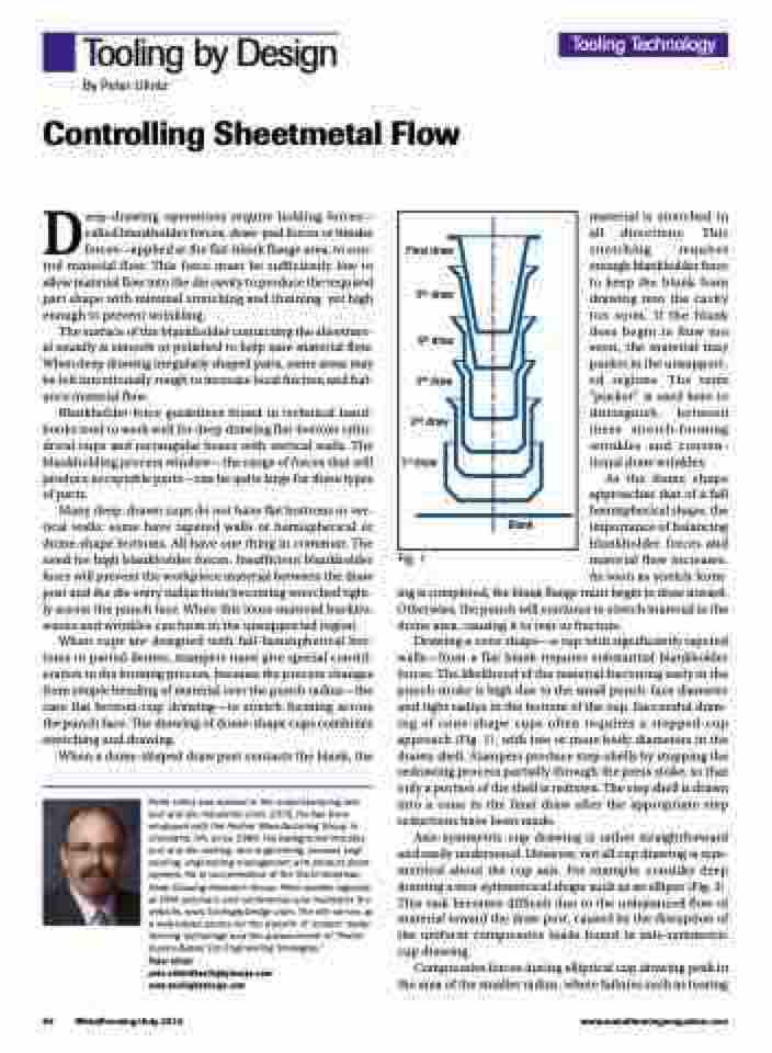
Final draw
5th draw
4th draw 3rd draw
2nd draw 1st draw
Blank
ing is completed, the blank flange must begin to draw inward. Otherwise, the punch will continue to stretch material in the dome area, causing it to tear or fracture.
Drawing a cone shape—a cup with significantly tapered walls—from a flat blank requires substantial blankholder forces. The likelihood of the material fracturing early in the punch stroke is high due to the small punch-face diameter and tight radius in the bottom of the cup. Successful draw- ing of cone-shape cups often requires a stepped-cup approach (Fig. 1), with two or more body diameters in the drawn shell. Stampers produce step-shells by stopping the redrawing process partially through the press stoke, so that only a portion of the shell is redrawn. The step shell is drawn into a cone in the final draw after the appropriate step reductions have been made.
Axis-symmetric cup drawing is rather straightforward and easily understood. However, not all cup drawing is sym- metrical about the cup axis. For example, consider deep drawing a non-symmetrical shape such as an ellipse (Fig. 2). This task becomes difficult due to the unbalanced flow of material toward the draw post, caused by the disruption of the uniform compressive loads found in axis-symmetric cup drawing.
Compressive forces during elliptical cup drawing peak in the area of the smaller radius, where failures such as tearing
54
MetalForming/July 2013
www.metalformingmagazine.com
