
Page 40 - MetalForming June 2013
P. 40
Bolting vs. Clamping
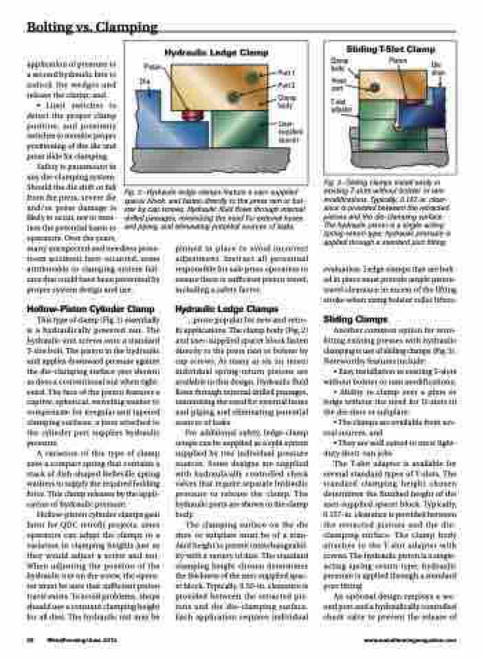
Hydraulic Ledge Clamp
Piston Die
Port 1
Port 2
Clamp body
User- supplied spacer
Clamp body
Hose port
T-slot adpator
Piston
Die shoe
SlidingT-Slot Clamp
application of pressure to a second hydraulic line to unlock the wedges and release the clamp; and
• Limit switches to detect the proper clamp position, and proximity switches to monitor proper positioning of the die and press slide for clamping.
Safety is paramount in
any die-clamping system.
Should the die shift or fall
from the press, severe die
and/or press damage is
likely to occur, not to men-
tion the potential harm to
operators. Over the years,
many unexpected and needless press- room accidents have occurred, some attributable to clamping-system fail- ures that could have been prevented by proper system design and use.
Hollow-Piston Cylinder Clamp
This type of clamp (Fig. 1) essentially is a hydraulically powered nut. The hydraulic unit screws onto a standard T-slot bolt. The piston in the hydraulic unit applies downward pressure against the die-clamping surface (not shown) as does a conventional nut when tight- ened. The face of the piston features a captive, spherical, swiveling washer to compensate for irregular and tapered clamping surfaces; a hose attached to the cylinder port supplies hydraulic pressure.
A variation of this type of clamp uses a compact spring that contains a stack of dish-shaped Belleville spring washers to supply the required holding force. This clamp releases by the appli- cation of hydraulic pressure.
Hollow-piston cylinder clamps gain favor for QDC retrofit projects, since operators can adapt the clamps to a variation in clamping heights just as they would adjust a screw and nut. When adjusting the position of the hydraulic nut on the screw, the opera- tor must be sure that sufficient piston travel exists. To avoid problems, shops should use a constant clamping height for all dies. The hydraulic nut may be
Fig. 3—Sliding clamps install easily in existing T-slots without bolster or ram modifications. Typically, 0.157-in. clear- ance is provided between the retracted pistons and the die-clamping surface. The hydraulic piston is a single-acting spring-return type; hydraulic pressure is applied through a standard port fitting.
evaluation. Ledge clamps that are bolt- ed in place must provide ample piston- travel clearance in excess of the lifting stroke when using bolster roller lifters.
Sliding Clamps
Another common option for retro- fitting existing presses with hydraulic clamping is use of sliding clamps (Fig. 3). Noteworthy features include:
• Easy installation in existing T-slots without bolster or ram modifications; • Ability to clamp over a plate or ledge without the need for U-slots in
the die shoe or subplate;
• The clamps are available from sev-
eral sources; and
• They are well suited to most light-
duty short-run jobs.
The T-slot adapter is available for
several standard types of T-slots. The standard clamping height chosen determines the finished height of the user-supplied spacer block. Typically, 0.157-in. clearance is provided between the retracted pistons and the die- clamping surface. The clamp body attaches to the T-slot adapter with screws. The hydraulic piston is a single- acting spring-return type; hydraulic pressure is applied through a standard port fitting.
An optional design employs a sec- ond port and a hydraulically controlled check valve to prevent the release of
38 MetalForming/June 2013
www.metalformingmagazine.com
Fig. 2—Hydraulic ledge clamps feature a user-supplied spacer block, and fasten directly to the press ram or bol- ster by cap screws. Hydraulic fluid flows through internal drilled passages, minimizing the need for external hoses and piping, and eliminating potential sources of leaks.
pinned in place to avoid incorrect adjustment. Instruct all personnel responsible for safe press operation to ensure there is sufficient piston travel, including a safety factor.
Hydraulic Ledge Clamps
...prove popular for new and retro- fit applications. The clamp body (Fig. 2) and user-supplied spacer block fasten directly to the press ram or bolster by cap screws. As many as six (or more) individual spring-return pistons are available in this design. Hydraulic fluid flows through internal drilled passages, minimizing the need for external hoses and piping and eliminating potential sources of leaks.
For additional safety, ledge-clamp setups can be supplied as a split system supplied by two individual pressure sources. Some designs are supplied with hydraulically controlled check valves that require separate hydraulic pressure to release the clamp. The hydraulic ports are shown in the clamp body.
The clamping surface on the die shoe or subplate must be of a stan- dard height to permit interchangeabil- ity with a variety of dies. The standard clamping height chosen determines the thickness of the user-supplied spac- er block. Typically, 0.50-in. clearance is provided between the retracted pis- tons and the die-clamping surface. Each application requires individual
