
Page 38 - MetalForming June 2013
P. 38
Manual Bolting vs. Hydraulic Clamping–
Press Uptime is
the Key Measurable
Metalformers should under- stand that hydraulic clamps are not required for quick die change (QDC). They should, however, consider automatic clamps whenever die-change times exceed 20 min., or when manual bolting fails to achieve sufficient press uptime. Further, varia- tions in manual bolting torque may not attain safe and consistent die- retention forces. Torque variation can cause process variability in some oper- ations. Of course, when manual bolting cannot be accomplished safely and consistently, power clamping offers a good alternative.
Hydraulic clamping systems often employ air-over-oil intensifier pumps to provide hydraulic pressure. These simple systems prove dependable, pro- vided the metalformer follows recom- mended maintenance procedures. Large systems, such as those on trans- fer presses with many clamps applied simultaneously, require large volumes of pressurized hydraulic fluid. Here, an electrical-motor-driven pump may be used to supply the required fluid volume. A hydraulic accumulator may be used to quicken clamping time.
A low-pressure hydraulic switch is a normal safety feature of air-over-oil and motor-driven hydraulic-pressure sources. By monitoring for a loss of
David Alkire Smith, a tool engineer with more than 50 years of experi- ence, is the editor of the “Die Design Handbook” and other engineering ref- erence works; dsmith@smithassoc.com, www.smithassoc.com.
...but never ignore the common practices offered here to ensure a failsafe design that provides safe die retention regardless of operating conditions.
BY DAVID ALKIRE SMITH
hydraulic pressure, a number of failure modes can be detected and the press stopped. Low-pressure safety switch- es vary in their setpoints—80 percent of the system’s operating pressure is typical.
General Safety Considerations
All automatic systems should be of failsafe design—that is, the die cannot become detached nor shift position on the ram or bolster during press opera- tion. This could occur due to a failure of the clamping-power source or by com- mand to release the clamps with the press in motion. To avoid this occur- rence, good designs incorporate some or all of these safety features:
• Dual hydraulic power sources across diagonal corners of the machine, much like the dual-brake system on automobiles;
• Pressure switches to detect a loss of holding force;
• Automatic press shutdown in case of loss of pressure;
• Over-center toggle-locking clamps that will hold in case of a loss of pressure;
• Hydraulic clamps with built-in check valves to prevent fluid release in case of a pressure failure—these require a second hydraulic line to
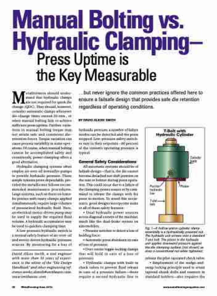
Fig. 1—A hollow-piston cylinder clamp essentially is a hydraulically powered nut. The hydraulic unit screws onto a standard T-slot bolt. The piston in the hydraulic unit applies downward pressure against the die-clamping surface (not shown) as does a conventional nut when tightened.
release the pilot-operated check valve; • Employment of the wedge-and- ramp locking principle used to retain tapered-shank drills and reamers in standard holders—also requires the
T-Bolt with Hydraulic Cylinder
Cylinder body
Port for hydraulic line
T-slot bolt
Piston
36 MetalForming/June 2013
www.metalformingmagazine.com
