
Page 41 - MetalForming June 2013
P. 41
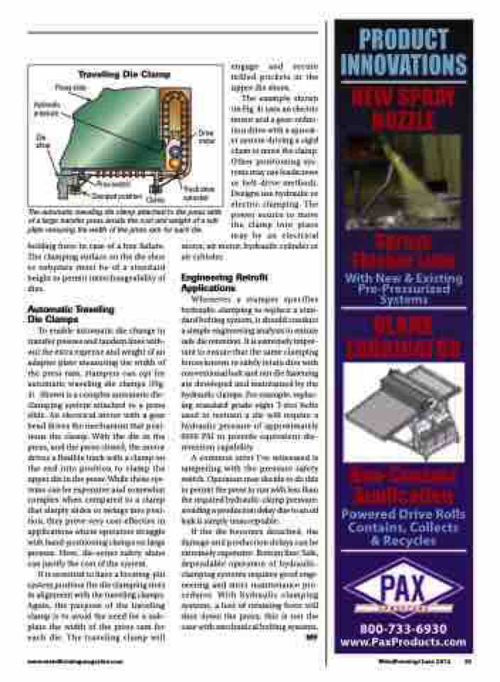
Traveling Die Clamp
Press slide
Hydraulic pressure
Die shoe
Drive motor
Track drive sprocket
Prox switch Clampedposition Clamp
The automatic traveling die clamp attached to the press slide of a large transfer press avoids the cost and weight of a sub plate mesuring the width of the press ram for each die.
engage and secure milled pockets in the upper die shoes.
The example shown (in Fig. 4) uses an electric motor and a gear-reduc- tion drive with a sprock- et system driving a rigid chain to move the clamp. Other positioning sys- tems may use leadscrews or belt-drive methods. Designs use hydraulic or electric clamping. The power source to move the clamp into place may be an electrical
������� �����������
�������� ������
������ �����������
���������������� ��������������� �������
����� ����������
����������� �����������
����������������� ����������������� ���������
������������ �������������������
holding force in case of a line failure. The clamping surface on the die shoe or subplate must be of a standard height to permit interchangeability of dies.
Automatic Traveling Die Clamps
To enable automatic die change in transfer presses and tandem lines with- out the extra expense and weight of an adapter plate measuring the width of the press ram, stampers can opt for automatic traveling die clamps (Fig. 4). Shown is a complex automatic die- clamping system attached to a press slide. An electrical motor with a gear head drives the mechanism that posi- tions the clamp. With the die in the press, and the press closed, the motor drives a flexible track with a clamp on the end into position to clamp the upper die in the press. While these sys- tems can be expensive and somewhat complex when compared to a clamp that simply slides or swings into posi- tion, they prove very cost-effective in applications where operators struggle with hand-positioning clamps on large presses. Here, die-setter safety alone can justify the cost of the system.
It is essential to have a locating-pin system position the die clamping slots in alignment with the traveling clamps. Again, the purpose of the traveling clamp is to avoid the need for a sub- plate the width of the press ram for each die. The traveling clamp will
motor, air motor, hydraulic cylinder or air cylinder.
Engineering Retrofit Applications
Whenever a stamper specifies hydraulic clamping to replace a stan- dard bolting system, it should conduct a simple engineering analysis to ensure safe die retention. It is extremely impor- tant to ensure that the same clamping forces known to safely retain dies with conventional bolt and nut die fastening are developed and maintained by the hydraulic clamps. For example, replac- ing standard grade-eight T-slot bolts used to restrain a die will require a hydraulic pressure of approximately 6000 PSI to provide equivalent die- retention capability.
A common error I’ve witnessed is tampering with the pressure safety switch. Operators may decide to do this to permit the press to run with less than the required hydraulic-clamp pressure; avoiding a production delay due to an oil leak is simply unacceptable.
If the die becomes detached, the damage and production delays can be extremely expensive. Bottom line: Safe, dependable operation of hydraulic- clamping systems requires good engi- neering and strict maintenance pro- cedures. With hydraulic clamping systems, a loss of retaining force will shut down the press; this is not the case with mechanical bolting systems.
MF
www.metalformingmagazine.com
MetalForming/June 2013 39
