
Page 44 - MetalForming August 2012
P. 44
The Science of Forming By Stuart Keeler
Tooling Technology
Dome Embossments Provide Forming Knowledge
Hemispherical embossments are found in millions of sheetmetal stampings. Though simple in shape, their deformation process can be complex. Ask tool and die personnel where the dome may fail and they’ll note several possibilities–straight line across the pole, the pole blows
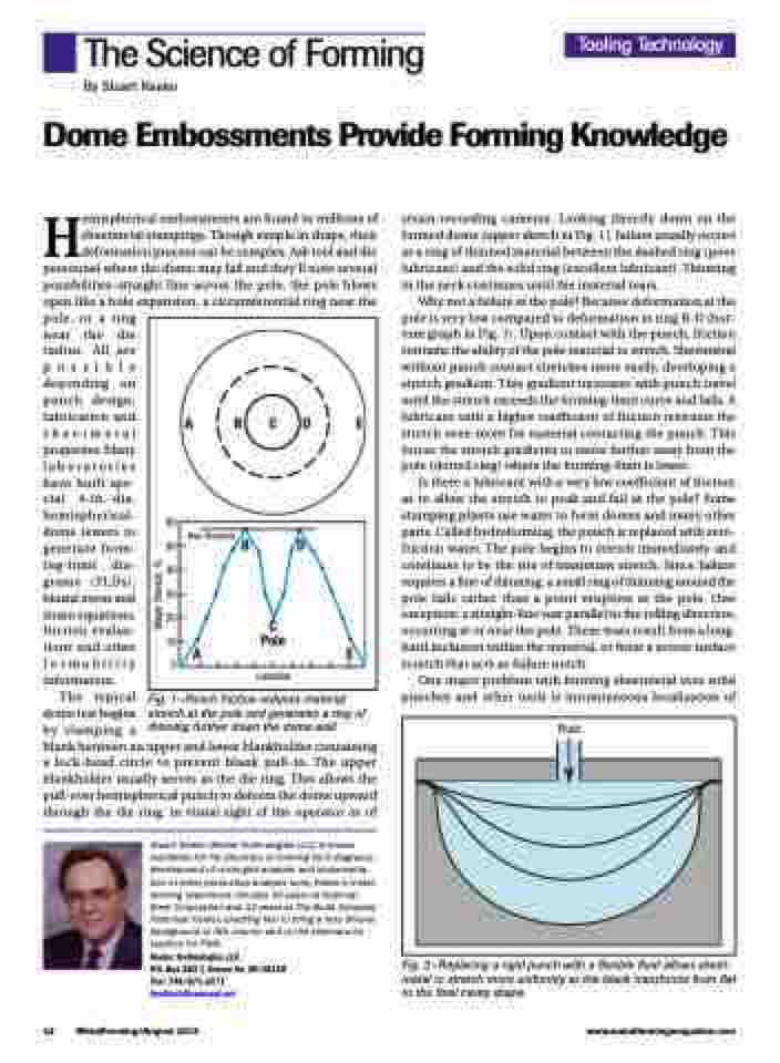
strain-recording cameras. Looking directly down on the formed dome (upper sketch in Fig. 1), failure usually occurs as a ring of thinned material between the dashed ring (poor lubricant) and the solid ring (excellent lubricant). Thinning in the neck continues until the material tears.
Why not a failure at the pole? Because deformation at the pole is very low compared to deformation in ring B-D (bot- tom graph in Fig. 1). Upon contact with the punch, friction restrains the ability of the pole material to stretch. Sheetmetal without punch contact stretches more easily, developing a stretch gradient. This gradient increases with punch travel until the stretch exceeds the forming-limit curve and fails. A lubricant with a higher coefficient of friction restrains the stretch even more for material contacting the punch. This forces the stretch gradients to move further away from the pole (dotted ring) where the forming-limit is lower.
Is there a lubricant with a very low coefficient of friction as to allow the stretch to peak and fail at the pole? Some stamping plants use water to form domes and many other parts. Called hydroforming, the punch is replaced with zero- friction water. The pole begins to stretch immediately and continues to be the site of maximum stretch. Since failure requires a line of thinning, a small ring of thinning around the pole fails rather than a point eruption at the pole. One exception: a straight-line tear parallel to the rolling direction, occurring at or near the pole. These tears result from a long, hard inclusion within the material, or from a severe surface scratch that acts as failure notch.
One major problem with forming sheetmetal over solid punches and other tools is instantaneous localization of
open like a hole pole, or a ring near the die radius. All are possible depending on punch design, lubrication and sheetmetal properties. Many laboratories have built spe- cial 4-in.-dia. hemispherical- dome testers to generate form- ing-limit dia- grams (FLDs), biaxial stress and strain equations, friction evalua- tions and other formability information.
The typical
dome test begins
by clamping a
blank between an upper and lower blankholder containing a lock-bead circle to prevent blank pull-in. The upper blankholder usually serves as the die ring. This allows the pull-over hemispherical punch to deform the dome upward through the die ring, in visual sight of the operator or of
Stuart Keeler (Keeler Technologies LLC) is known worldwide for his discovery of forming limit diagrams, development of circle-grid analysis and implementa- tion of other press-shop analysis tools. Keeler’s metal- forming experience includes 24 years at National Steel Corporation and 12 years at The Budd Company Technical Center, enabling him to bring a very diverse background to this column and to the seminars he teaches for PMA.
Keeler Technologies LLC
P.O. Box 283 | Grosse Ile, MI 48138 Fax: 734/671-2271 keeltech@comcast.net
expansion, a circumferential ring near the
60 50 40 30 20 10
0
ABCDE
Max. Allowable
BD
C
Pole AE
Location
Fig. 1—Punch friction reduces material stretch at the pole and generates a ring of thinning further down the dome wall.
Fluid
42 MetalForming/August 2012
www.metalformingmagazine.com
Fig. 2—Replacing a rigid punch with a flexible fluid allows sheet- metal to stretch more uniformly as the blank transforms from flat to the final cavity shape.
Major Stretch, %
