
Page 23 - MetalForming August 2012
P. 23
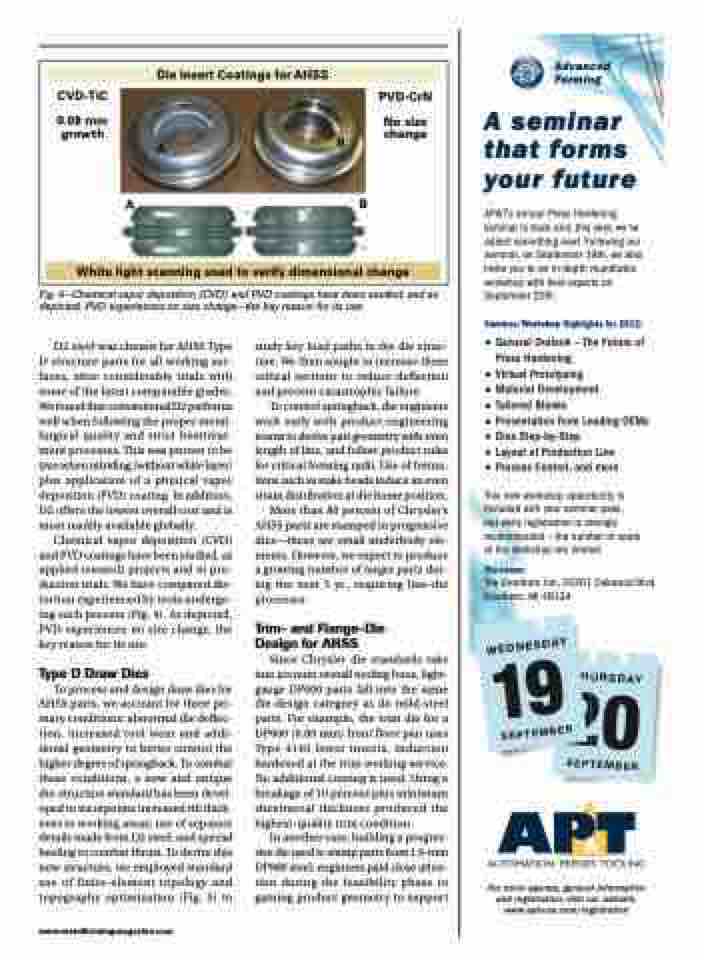
Die Insert Coatings for AHSS
CVD-TiC
0.08 mm growth
B
PVD-CrN
No size change
A
AB
White light scanning used to verify dimensional change
Fig. 4—Chemical vapor deposition (CVD) and PVD coatings have been studied, and as depicted, PVD experiences no size change—the key reason for its use.
Advanced Forming
A seminar that forms your future
AP&T’s annual Press Hardening seminar is back and, this year, we’ve added something new! Following our seminar, on September 19th, we also invite you to an in-depth roundtable �������� ���� ���� ������� �� September 20th.
Seminar/Workshop Highlights for 2012:
p General Outlook – The Future of Press Hardening
p Virtual Prototyping
p Material Development
p Tailored Blanks
p Presentation from Leading OEMs p Dies Step-by-Step
p Layout of Production Line
p Process Control, and more
This new workshop opportunity is included with your seminar pass,
but early registration is strongly recommended – the number of seats �� ��� �������� ��� ��������
The venue:
The Dearborn Inn, 20301 Oakwood Blvd. Dearborn, MI 48124
For more agenda, general information and registration, visit our website: www.apt-usa.com/registration
D2 steel was chosen for AHSS Type D structure parts for all working sur- faces, after considerable trials with some of the latest comparable grades. We found that conventional D2 performs well when following the proper metal- lurgical quality and strict heattreat- ment processes. This was proven to be true when nitriding (without white layer) plus application of a physical vapor deposition (PVD) coating. In addition, D2 offers the lowest overall cost and is most readily available globally.
Chemical vapor deposition (CVD) and PVD coatings have been studied, as applied research projects and in pro- duction trials. We have compared dis- tortion experienced by tools undergo- ing each process (Fig. 4). As depicted, PVD experiences no size change, the key reason for its use.
Type D Draw Dies
To process and design draw dies for AHSS parts, we account for three pri- mary conditions: abnormal die deflec- tion, increased tool wear and addi- tional geometry to better control the higher degree of springback. To combat these conditions, a new and unique die-structure standard has been devel- oped to incorporate increased rib thick- ness in working areas; use of separate details made from D2 steel; and special heeling to combat thrust. To derive this new structure, we employed standard use of finite-element topology and topography optimization (Fig. 5) to
study key load paths in the die struc- ture. We then sought to increase these critical sections to reduce deflection and prevent catastrophic failure.
To control springback, die engineers work early with product-engineering teams to derive part geometry with even length of line, and follow product rules for critical forming radii. Use of forma- tions such as stake beads induce an even strain distribution at die home position.
More than 80 percent of Chrysler’s AHSS parts are stamped in progressive dies—these are small underbody ele- ments. However, we expect to produce a growing number of larger parts dur- ing the next 5 yr., requiring line-die processes.
Trim- and Flange-Die Design for AHSS
Since Chrysler die standards take into account overall tooling force, light- gauge DP600 parts fall into the same die-design category as do mild-steel parts. For example, the trim die for a DP600 (0.80 mm) front floor pan uses Type 4140 lower inserts, induction hardened at the trim working service. No additional coating is used. Using a breakage of 10 percent plus minimum sheetmetal thickness produced the highest-quality trim condition.
In another case, building a progres- sive die used to stamp parts from 1.6-mm DP980 steel, engineers paid close atten- tion during the feasibility phase to gaining product geometry to support
www.metalformingmagazine.com
WEDNESDAY
19
SEPTEMBER
T
S
T
U
S
T
SE
H H
R R
SDAY
2
E
P
U
20
P
0
EMBER TE
