
Page 45 - MetalForming March 2012
P. 45
“Customer service is not a department, it’s a commitment.”
Christina Bartholomew, Customer Service Coordinator Schuler Incorporated
Setting the standards.
We set the standard for customer service, providing the timely answers and support you need to keep your systems running smoothly.
Unmatched Customer Service
To find out more, call 734.207.7200 or visit www.schulerinc.com
The Science of Forming
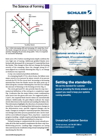
2
1
Yellow Marginal Zone
B
A
Green Safe Zone
True
Major Stretch
C Red
Failure Zone
3
True Minor Stretch
Fig. 2—Both decreasing (B) and increasing (C) metal flow from the binder changed the amount of stretch but not the forming severity. Changing the process along paths 1 thru 3 is required for successful stampings.
limit curve (FLC) before reaching home depth confirms the very high rate of tearing. Additional gridded blanks were formed with decreased (B) or increased (C) material flow from the binder. This change in flow did not change the forming severity of the stamping. Since the changes along B-A-C were aligned on a constant thinning line (Fig. 2), no change in thickness was expected.
A step-one numerical problem definition:
At a stamping depth 0.75 in. above home, the failure zone major stretch of yy percent by minor stretch of xx percent exceeds the FLC for the tryout steel. Increasing or decreasing material flow from the binder moves the data point up or down along the constant-thinning line, but does not change the amount of thinning or the forming severity (Fig. 2).
The circle grid and FLC also provide data for step two— numerical definition of the end goal or completion target. Fig. 2 indicates that the major/minor strain combinations must move into the green safe zone. For suggested paths 1, 2 and 3, the required final stretch values are automatically defined. Additionally, the grid ellipses indicate the major stretch directions in the material surrounding the failure site. This information highlights the direction of restrained sheet- metal flow. Instead of making blind deformation changes in the deformation zone, specific targeted changes can be made. Changes in workpiece-material properties, lubrication, tool design and other process parameters also can be stud- ied for a new defined end goal. Then, step three—numerical progress tracking—simply requires plotting data points from initial point A toward the goal defined in step two.
Virtual forming or computerized die tryout already pro- vides all of the data needed to implement the three-step trou- bleshooting process. Leading-edge companies are saving time and money by troubleshooting virtual stampings before machining the first die. MF
www.metalformingmagazine.com
MetalForming/March 2012 43
