
Page 44 - MetalForming March 2012
P. 44
The Science of Forming
By Stuart Keeler
Three Steps to Quicker Troubleshooting
Atroubleshooter was sent to pressline No. 5 when met- alformed parts began to tear. After evaluating the prob- lem, he tells the purchasing manager to order higher- quality steel, then instructs the die maker to grab a grinder and open up all of the punch-to-die clearances until the new steel arrives.
A simple problem has caused chaos, because the proposed solutions were offered without data. This amounts to guess- ing—ineffective troubleshooting. Data gathering would have required answers to these and other questions: Did the steel with splits have the same properties as the tryout steel? And, what exactly is better steel—more formable or less formable?
A press-shop riddle states: “Good steel is bad when bad steel is good.” If bad steel with poor formability proved suc- cessful during final die tryout, then good steel with excellent formability probably would not make the stamping, because the steel will form differently. A defined range of properties must be specified for consistent formability. Was any data available in the problem stated above to suggest the steel is a contributor?
The three steps to quicker troubleshooting were men- tioned briefly in last month’s column. Here we continue the discussion and provide a case study. The first step: Numer- ically defining the problem, which often is half of the prob- lem solution. Bad steel, insufficient lube, a rough punch—40 or more input variables could be the root cause of the prob- lem. More likely, an interaction of two or more input variables generated a major process change.
Tears in the stamping indicate a change in deformation or material flow. The current deformation pattern can be defined by circle grids etched into blanks. Leading-edge press shops will keep gridded panels saved from final die buy- offs of stampings. Many shops hang examples of their stamp- ings on the wall—why not make it a gridded stamping?
Numerically determining the deformation difference between the problem and the buyoff stampings provides one
Stuart Keeler (Keeler Technologies LLC) is known worldwide for his discovery of forming limit diagrams, development of circle-grid analysis and implementa- tion of other press-shop analysis tools. Keeler’s metal- forming experience includes 24 years at National Steel Corporation and 12 years at The Budd Company Technical Center, enabling him to bring a very diverse background to this column and to the seminars he teaches for PMA.
Keeler Technologies LLC
P.O. Box 283 | Grosse Ile, MI 48138 Fax: 734/671-2271 keeltech@comcast.net
definition of the problem. Step two is numerically defining the end target or goal. That information already is available from the gridded buyoff stamping.
Step three: Numerically tracking the corrective modifi- cations. Often, the modifications make the problem worse. These can be rapidly detected and altered before a stamper loses control of its metalforming processes.
Case in Point
An automotive stamping experiencing 100-percent splits during final die tryout illustrates the benefits of three-step troubleshooting. The failure area was located within the product but was fed material from the adjacent binder area. Increasing or decreasing the flow from the binder did not change the severity of the failure. Even more unusual, the amount of binder-metal flow into the critical area did not change the amount of thinning in the critical zone. After weeks of unsuccessful tryout, the stamper assigned a form- ing specialist from corporate R & D to the project.
Tooling Technology
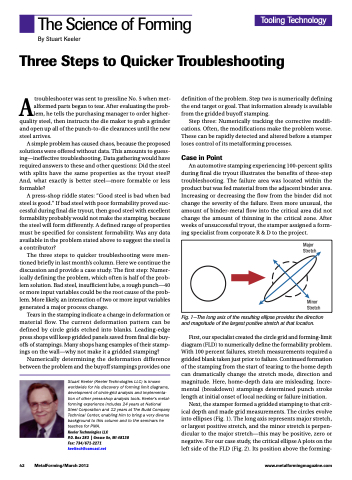
Major Stretch
Minor Stretch
Fig. 1—The long axis of the resulting ellipse provides the direction and magnitude of the largest positive stretch at that location.
First, our specialist created the circle grid and forming-limit diagram (FLD) to numerically define the formability problem. With 100 percent failures, stretch measurements required a gridded blank taken just prior to failure. Continued formation of the stamping from the start of tearing to the home depth can dramatically change the stretch mode, direction and magnitude. Here, home-depth data are misleading. Incre- mental (breakdown) stampings determined punch stroke length at initial onset of local necking or failure initiation.
Next, the stamper formed a gridded stamping to that crit- ical depth and made grid measurements. The circles evolve into ellipses (Fig. 1). The long axis represents major stretch, or largest positive stretch, and the minor stretch is perpen- dicular to the major stretch—this may be positive, zero or negative. For our case study, the critical ellipse A plots on the left side of the FLD (Fig. 2). Its position above the forming-
42 MetalForming/March 2012
www.metalformingmagazine.com
