
Page 37 - MetalForming February 2012
P. 37
locations on each end of the bumper, the area under the curves represents the average stretch in that area. The increased area under the driver-side curve indicates more stretch. Howev- er, the geometry of the two bumper ends is symmetrical and the amount of stretch should be equal. Therefore, the increase in the driver-side stretch probably originated from more restraint at the blank end. Less movement of binder material into the die requires a higher level of localized stretch. An off-center blank, less punch-die clearance, dif- ferential lubrication, a non-parallel press, varying lengths of cushion pins and other problems come to mind.
To reduce the list of potential causes, an engineer can con- duct this simple test, if the die allows: Rotate the die 180 deg. within the press and if the problem rotates with the die, die variables are suspect. If the problem stays on the same side of the press, press variables are targets for closer evaluation.
Same Conversation, Different Stampings
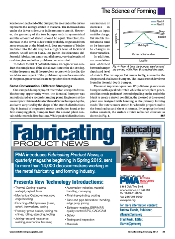
Our stamped-bumper project received an unexpected trou- bleshooting opportunity when the identical bumper was manufactured at a second stamping plant. Engineers at the second plant obtained data for three different bumper depths, and were surprised by the shape of the stretch distributions (Fig. 4). Instead of the peaked stretch distribution found at the first stamping plant, bumpers from the second plant con- tained flat stretch distributions. While peaked distributions
can increase or decrease in height as input variables change, flat stretch dis- tributions tend to be immune to changes in these variables.
In addition,
no correlation
was obtained
between bumper
depth and level
of stretch. The two upper flat curves in Fig. 4 were for the deepest and shallowest bumpers. The lowest stretch level was found in the mid-depth bumper.
The most important question: Why did one plant create bumpers with a peaked stretch while the other plant gener- ated flat stretch gradients? Instead of pulling on the end of the blank to create a stretch condition, the die used at the second plant was designed with bending as the primary forming mode. The outer convex stretch for a bend is proportional to the bend radius and sheet thickness. By keeping the bend radius constant, the surface stretch remained constant as
shown in Fig. 4.
MF
The Science of Forming
Plant A Plant B
Deep Shallow
Mid-depth
Corner radius location Location
Fig. 4—Plant A bent the bumper steel around the corner, while Plant B stretched the steel.
Fabricating
PRODUCT NEWS
PMA introduces Fabricating Product News, a quarterly magazine beginning in Spring 2012, sent to more than 14,000 decision-makers working in the metal fabricating and forming industry.
Presents New Technology Introductions:
An Official Publication of
6363 Oak Tree Blvd. Independence, OH 44131 Ph: 216/901-8800
Fax: 216/901-9669 www.pma.org
For more information contact: Andrew Flando, Publisher, aflando@pma.org
Brad Kuvin, Editor, bkuvin@pma.org
• Thermal Cutting—plasma, waterjet, oxyfuel, laser
• Mechanical Cutting—shear, saw, edge beveling
• Punching—CNC presses (turret, other), ironworkers, tooling
• Forming—press brakes, folding ma- chines, rolling, stamping, tooling
• Joining—arc and resistance welding, mechanical fastening
• Automation—robotics, material handling, conveying
• Finishing—grinding, coating
• Tube and pipe fabrication—bending, edge prep, joining
• Software—nesting, ERP/MRP, quality control/SPC, CAD/CAM
• Safety
• Testing and inspection • Materials
www.metalformingmagazine.com
MetalForming/February 2012 35
Stretch %
