
Page 36 - MetalForming February 2012
P. 36
The Science of Forming
By Stuart Keeler
Converse with Your Problematic Stampings
Tooling Technology
80
60
40
20
0
(MPa)
300 400 500 600
No Neck
Necked Maximum
allowable stretch
Safety factor
Actual
peak stretch Corner radius
40 50 60 70 80 90 Yield Strength (ksi)
Alate 1970s project evaluated how steel strength affect- ed forming severity of an automotive bumper formed from ground and flat polished hot-rolled steel. High- strength low-alloy steels with yield strengths of 45, 55, 65 and 80 ksi were formed in the same die with no changes to the
problem
while the
other stamp-
ing reveals
the solution.
Circle grids
provided
comparative
data (Fig. 3)
showing that
the driver side
of the bumper
underwent a
higher level of
stretch that
exceeded the
forming limit
curve, while
the passenger
side had a
peak stretch within the safe zone.
Three-Step Troubleshooting
Effective troubleshooting requires three pieces of data:
1) The current numerical definition or reference point of the problem. For this bumper, the upper curve in Fig. 3 rep- resents the high stretch distribution causing the failures.
2) A numerical end target or goal to indicate that the problem has been solved. An example: The lower curve with an adequate safety margin.
3) A numerical tracking process that indicates progress toward the target. While circle grids on the sheet surface prove useful for highlighting the details of the problem, these curves can be converted to thickness changes. An ultrason- ic thickness gauge can be used to rapidly track progress (or lack thereof) without the time consuming application of grids or the need to scrap the gridded stampings.
The two curves in Fig. 3 provide even more information. If the curves
encom- pass the exact same
Fig. 3—Driv- er end of the bumper encountered sporadic necks and tears.
X
Fig. 1—Stretch values measured using circle grids along line X-Y on the bumper wrap-around.
process inputs. The 90-deg. wrap-around was the prime area of interest (Fig. 1). The three lower-strength steels formed without defects, while the 80-ksi bumper experienced local necking in the radius. While engi- neers in this situation may have had little information at their fingertips, the stamping knew the severi-
Y
ty of the forming operation and was therefore interrogated for troubleshooting data using circle-grid analysis.
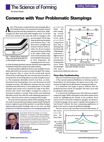
The first question addressed: How is your available stretch- ability affected by an increase in yield strength? The stamp- ing’s response (Fig. 2) comes via the actual peak stretch (bottom line) indicating that the steel becomes less able to retard growth of stretch gradients as yield strength increas- es. The maximum allowable stretch (top line), as deter- mined from the forming limit curve, also decreases as yield strength increases. The difference between the two curves represents the safety factor. A zero safety factor (77-ksi yield- strength steel) means we’ve reached the edge of the defor- mation cliff. Steels with higher strength are subject to increased necking or tearing. Peak stretch and maximum allowable stretch vary with the work-hardening exponent (n- value), which decreases with increasing yield strength.
The next obvious question asked of the stamping: Are the two ends of your production bumper symmetrical? During the project, engineers posed this question to a problem bumper experiencing sporadic breakage only on one end—an ideal problem for troubleshooting since one stamping displays the
Stuart Keeler (Keeler Technologies LLC) is known worldwide for his discovery of forming limit diagrams, development of circle-grid analysis and implementa- tion of other press-shop analysis tools. Keeler’s metal- forming experience includes 24 years at National Steel Corporation and 12 years at The Budd Company Technical Center, enabling him to bring a very diverse background to this column and to the seminars he teaches for PMA.
Keeler Technologies LLC
P.O. Box 283 | Grosse Ile, MI 48138 Fax: 734/671-2271 keeltech@comcast.net
Fig. 2—Stamping safety factor decreases as steel yield strength increases.
Driver Passenger
Forming Limit
Part Location
34 MetalForming/February 2012
www.metalformingmagazine.com
Stretch
Percent Stretch
