
Page 37 - MetalForming December 2011
P. 37
Tooling Technology
The Science of Forming
By Stuart Keeler
Are Laboratory Forming Tests Worthwhile?
The metalforming industry has many simulative test parts that laboratories use for predicting the formabil- ity of similar but much larger size configurations in actual stampings. Examples include Olsen stretch, limiting dome height, 4-in.-dia. hemispherical dome, Swift cup, Fukui conical, hole expansion, hydraulic bulge, Erichsen stretch and numerous bending operations. Historically, these tests have been used more in Europe and Asia than in North America. With the current intermingling of global industries, all groups using these tests should be aware of their deficiencies; the following discussion should generate great concern about the ability of lab tests to predict the per- formance of full-size stampings.
Consider these key process parameters, all of which can make or break a successful production-stamping run:
• Size
• Temperature
• Size/thickness ratio
• Lubrication
• Interface pressure
• Clamping
• Deformation history
• Edge quality
• Forming speed
• Specimen support
The values of these parameters in laboratory tests and dur-
ing production stamping usually differ by several magnitudes. Even worse, many laboratory tests are improperly conduct- ed, as noted below.
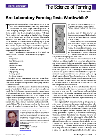
Olsen test: This test evaluates sheetmetal stretchability. A strip of material is locked over a 1-in.-dia. hemispherical punch (Fig. 1). As the punch moves upward, the material is sub- jected to biaxial stretch until the dome tears and the maximum height at failure recorded. Manual tests have a range of failure heights for a single sample depending on the ability of the operator to stop the test exactly at the onset of failure; auto- matic test machines may use maximum load detection as the onset of failure. The strip then moves along the die set until clearance is obtained to run another dome. This sequence
Stuart Keeler (Keeler Technologies LLC) is known worldwide for his discovery of forming limit diagrams, development of circle-grid analysis and implementa- tion of other press-shop analysis tools. Keeler’s metal- forming experience includes 24 years at National Steel Corporation and 12 years at The Budd Company Technical Center, enabling him to bring a very diverse background to this column and to the seminars he teaches for PMA.
Keeler Technologies LLC
P.O. Box 283 | Grosse Ile, MI 48138 Fax: 734/671-2271 keeltech@comcast.net
Fig. 1—Measuring stretchability limits by the Olsen test often is compromised by the flow of binder material into the dome.
continues until five domes have been formed and an average of the five heights computed and recorded as the measure of stretchability.
Unfortunately, other variables often influence failure height. For example, the test strip in Fig. 1 shows the binder feeding sheetmetal into the dome from two sides, due to improper binder lock- ing. This means the cross-strip direction is a combination of stretch and draw,
not pure stretching required by the test.
The lubricant applied to the sheetmetal affects stretch dis-
tribution and failure height. Even a constant lubricant type and quantity applied when the material is tested will not pro- vide a correct test. Ford Motor Co.’s Norbert Izworsky stud- ied the coefficient of friction when two different lubricants were both applied to the same sample. He found that the lubricant first applied to the sheetmetal fills the valleys in the surface topography, and the second lubricant applied on top simply is pushed out of the deformation zone by the die seg- ments. The coefficient of friction controlling material flow is that of the first lubricant—high-coefficient-friction slushing oil intended only for rust prevention or an excellent lubricant that also prevents rust formation.
For meaningful tests, all lubricant should be removed from the test strip and replaced by a constant test lubricant. Attempts to form parts dry create high variability and often galling. Testing galvannealed samples are especially difficult. This zinc-iron-alloy coating is like coral—once a lubricant enters the very hard porous structure, it proves extremely dif- ficult to remove.
Hole expansion test: This simple test (Fig. 2) begins by cre- ating a hole in the center of a square blank, placed on a die and clamped by the blank holder. A punch (typically conical, but hemispherical and flat punches also find use) expands the hole until the edges of the blank begin to crack. Edge stretch- ability (percent hole expansion) is determined by averaging the increase in hole diameters around the circle. However, test accuracy will vary with the edge quality of the hole. If a punch is used, severe cold working of the surrounding mate- rial significantly reduces the amount of residual edge stretch. A study conducted by Inland Steel’s R.R. Hilson, presented at Microalloying 75, showed a reduction of hole expansion from 280 percent for a milled hole (almost no damage) to 80 percent for a good-quality punched hole with 10-percent
www.metalformingmagazine.com
MetalForming/December 2011 35
