
Page 40 - MetalForming November 2011
P. 40
Tooling Technology
Tool Management Simplified
Fig. 2—Tool-control software parameters can be set to differ- ent material types and thicknesses for individual tools. This only is required to be set up once in the control, relieving the press operator from having to set tooling parameters for each combination of material and tooling.
setup sheets. Minimizing setups will optimize tool performance.
5 Maintenance and setup Tooling performance relates directly to the condi- tion of the holders and their alignment in the turret. Look here first when noticing premature tool wear, chipping, sticky punches and saw- tooth cutting with auto-index stations. With improvements in computer hard- ware and software, along with closer integration of the programming sys- tems, tool setup times are reduced, by having large, indexable, full-tonnage multi-tools to replace fixed tools at dif- ferent angles in a turret, and by the ability to have a built-in electronic tool
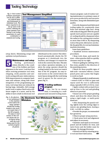
Fig. 3—An electron- ic tool whiteboard in the machine control alerts the setup operator should the tooling loaded in the turret not match that of the NC program. An easy-to-read screen on the con- trol shows the tur- ret layout along with the tools being used for the current program (in green).
whiteboard on the control. This white- board automatically checks the NC program as it downloads into the machine, and changes it to match the tools in the control at the time. This also can reduce operation mistakes, as it alerts the setup operator should the tooling loaded in the turret not match that of the NC program. An easy-to- read screen on the control shows the turret layout along with the tools being used (in green) for the current pro- gram (Fig. 3).
6 A tooling-wellness program
Last, but by no means least, is investing in a well- planned and executed tooling-main-
tenance program. Lack of routine tool- ing maintenance is a primary cause of poor press productivity and excessive downtime, along with diminished part quality.
Correctly sharpened and lubricated tooling makes for consistently clean holes and minimal edge burr, along with reduced slug pull. With the punch speeds turret presses now are capable of, tooling should be sharpened when the radius at the cutting point reaches no more than 0.005 in. By sharpening tools at this point, fabricators can dou- ble the grind life of a tool and minimize machine downtime.
Some basic guidelines:
• Establish written maintenance procedures.
• Keep tools clean, and watch for wear—when punches dull too quickly, clearance may be too tight.
• Remove galling by rubbing with a fine stone, parallel to the direction of the punching motion.
• Watch for these possible signs of dull tools—excessive rollover, a noise punch press and a press that begins to work too hard.
• Sharpen frequently, in small amounts —remove 0.001 to 0.002 in./pass and repeat until the tool is sufficiently sharp, typically 0.005 to 0.012 in. total.
• Apply coolant with as much force and as close to the tool and grinding wheel as is practical.
• Ensure use of the proper grinding wheel, and dress the wheel often by using a rigid single- or multi-point diamond.
• After sharpening the punch tool- ing, lightly stone the cutting edges to remove any grinding burrs, leaving a 0.001- to 0.002-in. radius.
• Provide the proper, recommended face geometry.
• Observe proper setup practices.
• Check press level and alignment and adjust as necessary.
• Examine (and repair as necessary) punch and die holders for wear, and turret bores and die-holder seats for damage. Fix damaged keyways.
• Extend tool life by ensuring prop- er tool and sheet lubrication. MF
An Electronic Tool Whiteboard Reduces Mistakes
38
MetalForming/November 2011
www.metalformingmagazine.com
