
Page 39 - MetalForming November 2011
P. 39
Tooling Technology
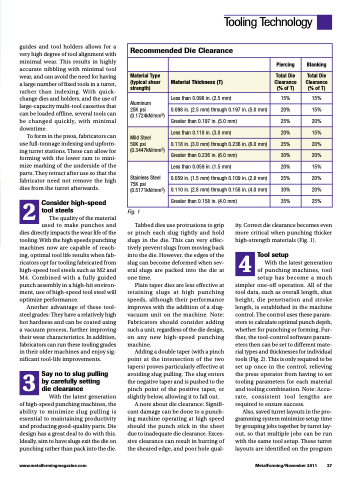
Recommended Die Clearance
Piercing
Blanking
Material Type (typical shear strength)
Material Thickness (T)
Total Die Clearance (% of T)
Total Die Clearance (% of T)
Aluminum
25K psi (0.1724kN/mm2)
Less than 0.098 in. (2.5 mm)
15%
15%
0.098 in. (2.5 mm) through 0.197 in. (5.0 mm)
20%
15%
Greater than 0.197 in. (5.0 mm)
25%
20%
Mild Steel
50K psi (0.3447kN/mm2)
Less than 0.118 in. (3.0 mm)
20%
15%
0.118 in. (3.0 mm) through 0.236 in. (6.0 mm)
25%
20%
Greater than 0.236 in. (6.0 mm)
30%
20%
Stainless Steel 75K psi (0.5171kN/mm2)
Less than 0.059 in. (1.5 mm)
20%
15%
0.059 in. (1.5 mm) through 0.109 in. (2.8 mm)
25%
20%
0.110 in. (2.8 mm) through 0.158 in. (4.0 mm)
30%
20%
Greater than 0.158 in. (4.0 mm)
35%
25%
guides and tool holders allows for a very high degree of tool alignment with minimal wear. This results in highly accurate nibbling with minimal tool wear, and can avoid the need for having a large number of fixed tools in a turret, rather than indexing. With quick- change dies and holders, and the use of large-capacity multi-tool cassettes that can be loaded offline, several tools can be changed quickly, with minimal downtime.
To form in the press, fabricators can use full-tonnage indexing and upform- ing turret stations. These can allow for forming with the lower ram to mini- mize marking of the underside of the parts. They retract after use so that the fabricator need not remove the high dies from the turret afterwards.
2 Consider high-speed tool steels
The quality of the material used to make punches and dies directly impacts the wear life of the tooling. With the high speeds punching machines now are capable of reach- ing, optimal tool life results when fab- ricators opt for tooling fabricated from high-speed tool steels such as M2 and M4. Combined with a fully guided punch assembly in a high-hit environ- ment, use of high-speed tool steel will
optimize performance.
Another advantage of these tool-
steel grades: They have a relatively high hot hardness and can be coated using a vacuum process, further improving their wear characteristics. In addition, fabricators can run these tooling grades in their older machines and enjoy sig- nificant tool-life improvements.
3 Say no to slug pulling by carefully setting
die clearance
With the latest generation of high-speed punching machines, the ability to minimize slug pulling is essential to maintaining productivity and producing good-quality parts. Die design has a great deal to do with this. Ideally, aim to have slugs exit the die on punching rather than pack into the die.
Fig. 1
Tabbed dies use protrusions to grip or pinch each slug tightly and hold slugs in the die. This can very effec- tively prevent slugs from moving back into the die. However, the edges of the slug can become deformed when sev- eral slugs are packed into the die at one time.
Plain taper dies are less effective at retaining slugs at high punching speeds, although their performance improves with the addition of a slug- vacuum unit on the machine. Note: Fabricators should consider adding such a unit, regardless of the die design, on any new high-speed punching machine.
Adding a double taper (with a pinch point at the intersection of the two tapers) proves particularly effective at avoiding slug pulling. The slug enters the negative taper and is pushed to the pinch point of the positive taper, or slightly below, allowing it to fall out.
A note about die clearance: Signifi- cant damage can be done to a punch- ing machine operating at high speed should the punch stick in the sheet due to inadequate die clearance. Exces- sive clearance can result in burring of the sheared edge, and poor hole qual-
ity. Correct die clearance becomes even more critical when punching thicker high-strength materials (Fig. 1).
4 Tool setup
With the latest generation
of punching machines, tool
setup has become a much simpler one-off operation. All of the tool data, such as overall length, shut height, die penetration and stroke length, is established in the machine control. The control uses these param- eters to calculate optimal punch depth, whether for punching or forming. Fur- ther, the tool-control software param- eters then can be set to different mate- rial types and thicknesses for individual tools (Fig. 2). This is only required to be set up once in the control, relieving the press operator from having to set tooling parameters for each material and tooling combination. Note: Accu- rate, consistent tool lengths are required to ensure success.
Also, saved turret layouts in the pro- gramming system minimize setup time by grouping jobs together by turret lay- out, so that multiple jobs can be run with the same tool setup. These turret layouts are identified on the program
www.metalformingmagazine.com
MetalForming/November 2011 37
