
Page 46 - MetalForming September 2011
P. 46
Metalforming Electronics
By George Keremedjiev
Three Critical Steps to Die-Protection Excellence at HTT
Clarity, focus and precise execution are the hallmarks of the die-protection program at HTT, Inc., Sheboygan Falls, WI. Its exemplary error-proofing program has existed for about a year, and in that short time it has propelled the company into sensor applications rivaling those of much more experienced metalformers.
HTT, founded in 1985 as High Tech Tool & Die, Inc., serv- ices clients in the automotive, white goods, plumbing, diesel, small-engine and fire-suppression sectors. Its facility includes a comprehensive toolroom, and its list of capabilities includes prototyping, production machining with CNC machining
centers, wire EDM, waterjet cutting and stamping on presses from 45 to 400 tons. Certifications include QS- 9000, ISO, TS compliance and upcoming TS certification in 2012.
In the sum- mer of 2010, HTT launched a sensor-based error-proofing manufacturing program, and appointed Alan Wittkopp sensor applications specialist. Wittkopp brought 23 years of experience as a journeyman tool and die maker to the position, and in short order mastered the intricacies of inductive and photoelectric sensors through a series of intense hands-on assignments. Once reaching a certain comfort level with the sensors, Witt- kopp began to implement them in HTT’s tooling. His method- ical and well-thought-out approach to the correct uses of
electronic sensors in dies is worthy of some detail here. For starters, Wittkopp believes firmly in the importance of
George Keremedjiev has been writing this column for more than 20 years. He regularly consults with metal- forming companies worldwide and provides metal- formers with training on the application and imple- mentation of sensors for die protection. For more information on his seminars and consultancies, con- tact:
Tecknow Education Services, Inc.
P.O. Box 6448
Bozeman, MT 59771
tel: 406/587-4751 | fax: 406/587-9620 www.mfgadvice.com
gk@mfgadvice.com
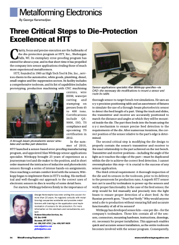
Sensor-applications specialist Alan Wittkopp specifies—via CAD—the necessary die modifications to mount a sensor and route its cable.
thorough sensor-to-target bench-test simulations. He uses an x-y-z precision positioning table and an assortment of fixtures to simulate the use of a through-beam photoelectric sensor to detect the feed length of a part. Using the track and slides, the transmitter and receiver are accurately positioned to match the distance and angles at which they will be mount- ed inside the die. The part then feeds into the beam using the x-y-z mechanism to ensure precise feed detection to the requirements of the die. After numerous iterations, the cor- rect position of the sensor relative to the part’s edge is deter- mined.
The second critical step is modifying the die design to properly contain the sensor’s transmitter and receiver to the exact relationship to the part achieved on the test bench. Transmitter and receiver positions—including the angle of the light as it touches the edge of the part—must be duplicated within the die to achieve the correct feed detection. I cannot overemphasize this step—it is crucial to the success of any sensor application.
The third critical requirement: A thorough inspection of the die and its sensors in the toolroom, prior to its delivery to the pressroom for production runs. A superb HTT sensor test cart is used by toolmakers to power-up the sensors and verify proper functionality. In the case of the feed sensor, the strip would be fed manually and precisely into the light beam to ensure proper detection of a short feed. As the Russian proverb goes, “Trust but Verify.” Why would anyone send a die to production without ensuring full and accurate functionality of all of its sensors?
Wittkopp has developed sensor kits—one per die—for the company’s toolmakers. These kits contain all of the sen- sors, connectors, mounting hardware, instructions, drawings, etc. necessary for proper installation. This approach enables quick and accurate sensor installation, as the entire toolroom becomes involved with the sensor program. Consequently,
A through-beam photoelectric sensor simu- lates and verifies part detection.
44
MetalForming/September 2011
www.metalformingmagazine.com
