
Page 44 - MetalForming September 2011
P. 44
Tooling by Design
By Peter Ulintz
Material Gainers
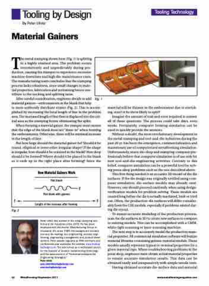
The metal stamping shown here (Fig. 1) is splitting in a highly strained area. The problem occurs intermittently and unpredictably during pro- duction, causing the stamper to experience excessive machine downtime and high die-maintenance costs. The manufacturing team concludes that the stamping process lacks robustness, since small changes in mate- rial properties, lubrication and restraining forces con- tribute to the necking and splitting issue.
Tooling Technology
After careful consideration, engineers decide to add material gainers—embossments in the blank that help
to more uniformly distribute strains (Fig. 2). This is accom- plished by increasing the local length of line in the problem area. The increased length of line then is displaced into the crit- ical area as the stamping forms; eliminating the splits.
When forming a material gainer, the stamper must ensure that the edge of the blank does not “draw-in” when forming the embossments. Otherwise, there will be minimal increase in the length of line.
But how large should the material gainer be? Should it be round, elliptical or some other irregular shape? If the shape is irregular, how should it be oriented in the blank? How deep should it be formed? Where should it be placed in the blank so it ends up in the right place after forming? Since the
Fig. 1
How Material Gainers Work
Flat blank
F
FF
Length of line increase after forming
Flat blank with gainers
Fig. 2
material will be thinner in the embossment due to stretch- ing, won’t it be more likely to split?
Imagine the amount of trail and error required to answer all of these questions. The process could take days, even weeks. Fortunately, computer forming simulation can be used to quickly provide the answers.
Without a doubt, the most revolutionary development in the metal-stamping and tool-and-die industries during the past 20 yr. has been the emergence, commercialization and mainstream use of computerized metalforming simulation. Unfortunately, many die-shop and stamping-company pro- fessionals believe that computer simulation is of use only for new tool-and-die-engineering activities. Contrary to this belief, computer simulation can be a powerful tool for solv- ing press-shop problems such as the one described above.
This first thing needed is an accurate 3D model of the die surfaces. If the die design was originally verified using com- puter simulation, die-surface models may already exist. However, one should proceed cautiously when using design- verification models for problem solving. These models are created long before the die is actually machined, built or tried out. Often, the production-die surfaces will differ consider- ably from the CAE models, especially if problems existed dur- ing die tryout.
To ensure accurate modeling of the production process, scan the die surfaces in 3D to create new surfaces to compare to existing models. This can be accomplished with a CMM, white-light scanning or laser-scanning machine.
The next step is to accurately model the production mate- rial properties. All commercial simulation software will feature material libraries containing generic material models. These models usually represent typical or nominal properties for a given material type. When troubleshooting problems in the press shop, engineers must obtain actual material properties to ensure accurate simulation results. This data can be obtained easily and inexpensively with simple tensile tests.
Having obtained accurate die-surface data and material
42 MetalForming/September 2011
www.metalformingmagazine.com
Peter Ulintz has worked in the metal stamping and tool and die industries since 1978. He has been employed with the Anchor Manufacturing Group in Cleveland, OH, since 1989. His background includes tool and die making, tool engineering, process engi- neering, engineering management and product devel- opment. Peter speaks regularly at PMA seminars and conferences and maintains the website, www.Tooling- byDesign.com. The site serves as a web-based source for the transfer of modern metalforming technology and the advancement of “Performance-Based Die Engineering Strategies.”
Peter Ulintz
pete.ulintz@toolingbydesign.com www.toolingbydesign.com
