
Page 45 - MetalForming September 2011
P. 45
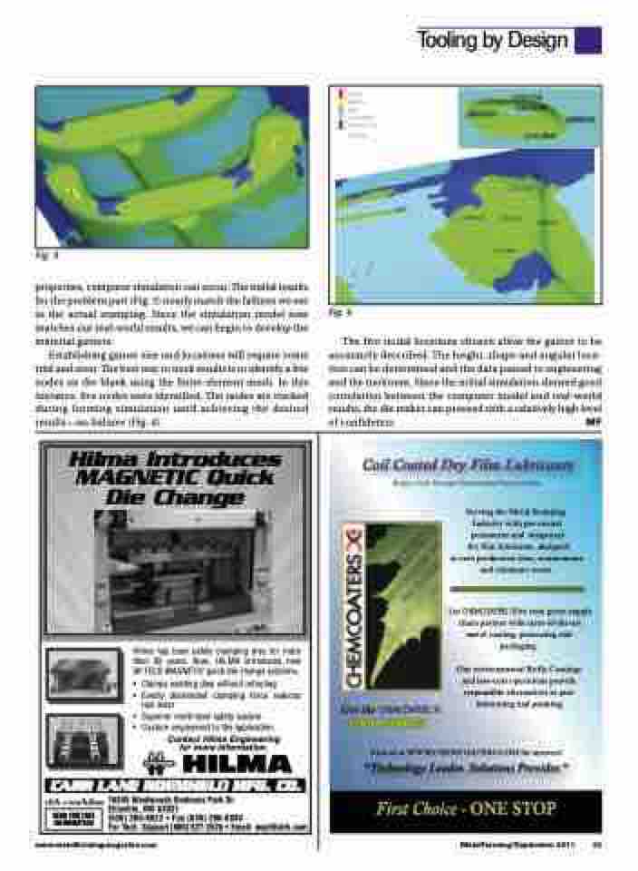
 Fig. 3
properties, computer simulation can occur. The initial results for the problem part (Fig. 3) nearly match the failures we see in the actual stamping. Since the simulation model now matches our real-world results, we can begin to develop the material gainers.
Establishing gainer size and locations will require some trial and error. The best way to track results is to identify a few nodes on the blank using the finite-element mesh. In this instance, five nodes were identified. The nodes are tracked during forming simulation until achieving the desired results—no failures (Fig. 4).
Hilma Introduces MAGNETIC Quick Die Change
Hilma has been safely clamping dies for more than 50 years. Now, HILMA introduces new M-TECS MAGNETIC quick die change systems.
• Clampsexistingdieswithoutretooling
• Evenly distributed clamping force reduces
tool wear
• Superiormulti-levelsafetysystem
• Customengineeredtotheapplication.
Contact Hilma Engineering for more information.
clrh.com/hilma 16345 Westwoods Business Park Dr.
SEND FOR FREE INFORMATION
Fig. 4
The five nodal locations chosen allow the gainer to be accurately described. The height, shape and angular loca- tion can be determined and the data passed to engineering and the toolroom. Since the initial simulation showed good correlation between the computer model and real-world results, the die maker can proceed with a relatively high level
www.metalformingmagazine.com
MetalForming/September 2011 43
Ellisville, MO 63021
(636) 386-8022 • Fax (636) 386-8034
For Tech. Support (800) 827-2526 • Email: engr@clrh.com
of confidence.
MF
Tooling by Design
