
Page 44 - MetalForming August 2011
P. 44
Tooling by Design By Peter Ulintz
Surface Coatings for Draw Steels— A Time and a Place
Tooling Technology
The tool and die and metal- forming industries spend a significant amount of money on specialized surface coatings for die components. The primary pur- pose of these coatings is to protect the tool surface against abrasive, adhesive, and corrosive wear. The surface coating’s high hardness and low friction coefficient often can help increase tool life during pro- duction.
However, there are applications
when surface coatings are unnec-
essarily applied. This occurs when
metalformers fail to detect other
process errors causing premature
tool wear, such as faulty programming, machining or assem- bly practices. In these instances, the coating appears to improve tool life and productivity, but in actuality the coat- ing only adds to the cost of die construction and maintenance.
Applying a surface coating to a die section often is the first response when galling occurs in the corner of a rectangular box or other irregularly shaped draws. If the coating works, the situation worsens, as someone suggests that the company alter its die-design standards to require a surface coating on all dies of similar design or producing similar parts. This adds unnecessary cost to the company’s dies, because the future dies will be designed and built to a standard that accom- modates poor die-construction techniques—a worst-case scenario.
If you prefer to do things more methodically and wish to keep your tooling and production costs under control, then read on.
The advent of CAD models and CNC machining has sub- stantially reduced the amount of time required to design, machine and assemble stamping dies. One practice for machining draw and form dies is to machine clearance
Peter Ulintz has worked in the sheetmetal-forming industry since 1978. His background includes tool and die making, tool and process engineering, engi- neering management and product development. Peter also operates the website www.ToolingbyDesign.com, a source for the transfer of modern metalforming and tool-and-die technology, and which promotes the use of “Performance-Based Die Engineering Strategies.” Peter Ulintz
pete.ulintz@toolingbydesign.com www.toolingbydesign.com
between the punch and die cavi- ty by offsetting the CNC cutter path by maximum material thick- ness. This works well, until a drawn corner is encountered.
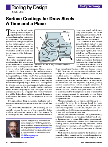
The corners in box-shaped geometries form similarly to cup drawing. If the four straight walls of the box are removed so that the corners join together, they form a cylindrical cup. These corners are compressive on the workpiece material moving toward the die radius, and tensile on the material drawn over the radius (see the fig- ure). As a result, thickening occurs in the vertical wall (A) and the
flange remaining on the draw pad (B) near the draw corners. This thickening phenomenon sometimes is overlooked during CNC programming and machining. Worse yet, the
condition may not be identified.
To reduce the likelihood of galling in drawn corners,
additional punch-to-die clearance must be machined in the vertical wall area. This may sound easy, but it generally requires analytical tools such as computer simulation. A properly executed metalforming simulation can provide accurate thickness plots in drawn parts, which can be used to assess material thickening locations and determine the correct clearance needed for a particular process. In the absence of this data, stampers can use tables found in die- design handbooks.
After machining the proper clearances in the drawn cor- ners, polish the corner die sections as though they were going to have a surface coating applied and install the uncoated components in the die. You may find that a thor- ough polishing will yield the performance improvements pre- viously attributed to surface coatings.
Another phenomenon to consider: During metalforming, plastic deformation and friction generate heat, which caus- es die components to expand. This can decrease the punch- die clearances machined into the tool. If this clearance is suf- ficiently reduced, excessive stretching can occur and the stamping may eventually tear or break. When this occurs, the metalformer often decides to reduce press speed to minimize heat generation.
A better solution: Increase punch-to-die clearance to allow for predicted tool expansion at the expected operating tem- perature. This might require scrapping a few stampings or pre-
A
B
Stretch bend
Bend and
Box CL
Stretch bend
Bend and straighten
straighten
Compression
The corner of a box or irregular draw corner forms like a cup.
42 MetalForming/August 2011
www.metalformingmagazine.com
