
Page 43 - MetalForming April 2011
P. 43
Sensor Basics
The types of sensors appropri- ate for use with IDT are those capable of detecting the physical presence (or absence) of an object. These sensors are generally con- figured for use with low-voltage (3-24 V DC) logic circuits. The most suitable types:
• Mechanical contact switch- es—the least costly option, but generally may have a shorter life expectancy than noncontact alter- natives.
• Photo-optic sensors—work on the principle of an interrupted light beam, and are available in several configurations:
1) Separate emitter and receiver;
2) Retroreflective—Emitter and receiver are contained within a single assembly, with a separate mirror to reflect the beam;
3) Diffuse-reflective—Emitter and receiver are contained within a single assembly and the object to be detected reflects the light beam.
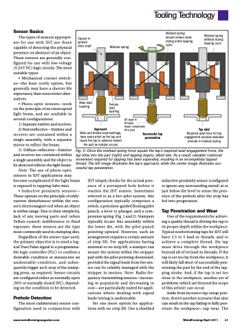
Fig. 3—Once the misfeed spring force equals the tap’s required axial engagement force, the tap bites into the part (right) and tapping begins, albeit late. As a result, valuable rotational movement required for tapping has been expended, resulting in an incompletely tapped thread. The left image illustrates the tap’s approach, while the center image illustrates suc- cessful tap penetration.
Tooling Technology
Square or splined drive shaft
Misfeed spring should remain static during entire tapping cycle
Misfeed spring deflects during tapping cycle
Male lead bushing
Male and female lead bushings, have same pitch as the tap and cause the tap to advance toward the part as rotation occurs
Approach
All lead-in threads
travel completely thru part
Successful tap penetration
Tap skid
Misfeed spring
Female lead bushing
Required axial force for tap engagement exceeds available preload in misfeed spring
Note: The use of photo-optic sensors in IDT applications may become complicated if the light beam is exposed to tapping-lube mist.
• Inductive proximity sensors— These operate on the principle of eddy- current disturbances within the sen- sor’s electromagnet coil when an object is within range. Due to their simplicity, lack of any moving parts and (when Teflon-coated) indifference to fluid exposure, these sensors are the type most commonly used in stamping dies.
Regardless of the sensor type used, the primary objective is to send a log- ical True/False signal to a programma- ble logic controller (PLC) to confirm a desirable condition or annunciate an undesirable condition, and subse- quently trigger an E-stop of the stamp- ing press, as required. Sensor circuits are configured either as normally open (NO) or normally closed (NC), depend- ing on the condition to be detected.
Prehole Detection
The most rudimentary sensor con- figuration used in conjunction with
IDT simply checks for the actual pres- ence of a pretapped hole before it reaches the IDT station. Sometimes referred to as a hot-pilot system, this configuration typically comprises a switch, a precision-guided floating pilot punch, a lever or plunger, and a com- pression spring (Fig. 1 and 2). Stampers typically locate this assembly within the lower die, with the pilot punch pointing upward. However, such an arrangement requires a certain amount of strip lift. For applications having minimal or no strip lift, a stamper can mount the system within the stripper pad with the pilot pointing downward, provided the signal leads from the sen- sor can be reliably managed with the stripper in motion. Note: Radio-fre- quency-transmitting sensors—increas- ing in popularity and decreasing in cost—are particularly suited for appli- cations where dealing with signal leads/wiring is undesirable.
Yet one more option for applica- tions with no strip lift: Use a shielded
inductive-proximity sensor (configured to ignore any surrounding metal) at or just below die level to sense the pres- ence of the prehole after the strip has fed into progression.
Tap Penetration and Wear
One of the requirements for achiev- ing a quality thread is driving the tap to its proper depth within the workpiece. Typical nonbottoming taps for IDT will have 2.5 to 5 lead-in threads, and to achieve a complete thread, the tap must drive through the workpiece beyond all of its lead-in threads. If the tap is set too far from the workpiece, it will likely fall short of successfully pen- etrating the part by the end of the tap- ping stroke. And, if the tap is set too close to the workpiece, another set of problems (which are beyond the scope of this article) can occur.
Aside from incorrect tap-setup posi- tion, there’s another scenario that also can result in the tap failing to fully pen- etrate the workpiece—tap wear. The
www.metalformingmagazine.com
MetalForming/April 2011 41
