
Page 21 - MetalForming September 2010
P. 21
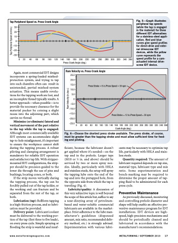
  Fig. 5—Graph illustrates peripheral tap speeds (while the tap is engaged in the material) for three different IDT alternatives for a stainless-steel appli- cation. Red and blue curves give speed profiles for direct-drive and exter- nal drivescrew IDT devices, while the yellow curve represents the speed profile for a cam- actuated internal drive- screw IDT device.
  Ram Velocity vs. Press Crank Angle
25.0 20.0 15.0 10.0
5.0 0 –5.0 –10.0 –15.0 –20.0 –25.0
Press Stroke = 6 in./Press Speed = 30 spm
Press Stroke = 12 in./Press Speed = 30 spm
0 20 40 60 80100120140160180200220240260280300320340360 Crank Angle (deg.)
Fig. 6—Choose the shortest press stroke available. The press stroke, of course, must be greater than the tapping stroke and must allow sufficient time for feed- ing and piloting.
 Tap Peripheral Speed vs. Press Crank Angle
30 20 10
0 –10 –20 –30
0 20 40 60 80 100 120 140 160 180 200 220 240 260 280 300 320 340 360 Press Crank Angle (deg.)
                                                 Again, most commercial IDT designs incorporate a spring-loaded misfeed- protection system, and trying to tap into such chamfers often can result in unintended, partial misfeed-system actuation. This means usable revolu- tions for the tapping work are lost, and an incomplete thread typically results. A better approach—when possible—is to provide the necessary clearance for the material pucker by coining a slight recess into the adjoining part, which carries no thread.
Minimize (or eliminate) lateral and vertical movement of the part relative to the tap while the tap is engaged: Although most commercially available IDT systems can accommodate slight tap-to-hole misalignment, it’s important to ensure the workpiece cannot shift during the tapping process. A robust piloting and clamping arrangement is mandatory for reliable IDT operation and satisfactory tap life. With stripper- mounted IDT configurations, the strip- per should be precision guided to the lower die through the use of pins and bushings, locating cones, or both.
If the strip moves vertically during the tapping process, the tap can be forcibly pulled out of the tap holder, or the working end can fracture and be separated from the rest of the tap, or both.
Lubrication (tap): Rollform tapping is a high-friction process, and so lubri- cation must be provided.
Delivery point: Lubricant/coolant must be delivered to the working por- tion of the tap (first three to five leads), on every press cycle. Simply spraying or flooding the strip is wasteful and insuf-
ficient, because the lubricant doesn’t get applied where it’s needed—on the tap and in the prehole. Larger taps (M10 or 3⁄8 in. and above) should be serviced by two or more spray noz- zles. Ideally, particularly with HSLA and stainless steels, the setup will spray the tapping lube onto the end of the tap and into the pretapped hole, from the opposite side from which the tap is traveling (Fig. 4).
Lubricity/quality: A discussion of this very subjective topic is well beyond the scope of this article but, suffice to say a near-dizzying array of petroleum- based and water-soluble commercial lubricants are available in the market- place. Strict adherence to the lube man- ufacturer’s guidelines (dispensed amount, mix ratio, recommended deliv- ery method, etc.) is strongly advised. Experimentation with various lubri-
cants may be necessary to optimize tap life, particularly with HSLA and stain- less steels.
Quantity required: The amount of lubricant required depends on tap size, material type, lubricant type and mix ratio. Some experimentation and bench-marking may be required to determine the proper amount of tap- ping fluid to be administered for each press cycle.
Preventive Maintenance
As previously discussed, monitoring and controlling prehole diameter and shape will help enable an effective pre- ventive-maintenance program for IDT installations. IDT devices are high- speed, high-precision mechanisms and should be periodically cleaned and lubricated in accordance with the manufacturer’s recommendations.
www.metalformingmagazine.com
METALFORMING / SEPTEMBER 2010 17
Ram Velocity (in./sec.)
Tap Peripheral Speed (m/min.)
