
Page 20 - MetalForming September 2010
P. 20
In-DieTapping
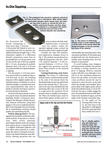
Fig. 3—The nature of rollforming threads causes a small material puck- er at the ends of the thread where the thread terminates at the top and bot- tom faces of the material.
the theoretical
thread. Attempting to
form more than 75 percent
of theoretical full thread is never rec- ommended and will not produce any additional thread strength (Fig. 1). The substantive rigidity of a rollformed thread’s crosssection comes from its pyramidal base, not the geometry near its crest. In the case of the ever-popular M6 x 1.0 size, decreasing the prehole diameter from 5.56 mm to 5.50 mm can nearly double the required dynam- ic tapping.
Two key points: A 5.56-mm extru- sion punch will not actually produce a 5.56-mm hole. In fact, the resulting diameter will be slightly smaller due to material memory or elasticity, so a bit of tribal knowledge (or perhaps trial-and- error experimentation) may come in handy in smartly arriving at a particu- lar desired prehole diameter.
Second, as the pierce punch or extru- sion punch wears, the prehole diameter gradually shrinks. Continuous moni- toring of the diameter, whether by peri- odic manual verification using hard gauges or by a more sophisticated hot- pilot sensoring approach, proves help- ful in maintaining consistent thread quality and optimizing tap life.
Prehole shape/geometry: The pre- tapped hole should be uniformly cylin- drical and free of any burrs or aberra- tions. With certain materials, particularly stainless steels, the stamper may need to pierce or extrude the hole to a slightly undersized diameter and then shave away material in a subse- quent die station to bring the hole pre- cisely to the desired diameter and cylin- dricity. Shaving operations also can
full
Apply Lube to the Tap and into the Prehole
Clearance gap, g
T, total depth to tap
Tapping Lube Spray Point #1
t
Dp, prehole diameter
Tapping Lube Spray Point #2
16 METALFORMING / SEPTEMBER 2010
www.metalformingmagazine.com
Fig. 2—The pretapped hole should be uniformly cylindrical and free of any burrs or aberrations. With certain materi- als, particularly stainless steels (shown here), the stam-
per may need to pierce or extrude the hole to a slightly undersized diameter and then shave
away material in a subsequent die station to bring the hole precisely to the
desired diameter and cylindricity.
serve to remove the thin work-
hardened layer of material near the surface, reduce the required tapping torque, extend tap life and produce better-quality threads. Consider the Type 304 stainless- steel application example shown in Fig. 2. The prehole was produced in a single die progression (tap size = M8 x 1.25, prehole diameter = 0.294 in., material thickness = 0.156 in.). Note the ragged hole geometry and the heavy burrs present on the material
fracture side.
Coining/chamfering a hole before tapping: The nature of rollforming threads causes a small material pucker at the ends of the thread where the thread terminates at the top and bottom faces of the material (Fig. 3). This is nor- mal. In the case of an extruded hole, this puckering effect also occurs at the exit or rough end of the extrusion, but its presence there is usually inconsequen- tial. When the finished piece must be mated flush against another part in a
subassembly, this material pucker often can present problems. If the pucker gets pushed back into the thread space, it usually causes binding issues once the fastener is introduced.
To avoid binding, some designers will instinctively chamfer the prehole by adding a coining operation just prior to tapping. However, material pucker will still occur, although it now will sit in the chamfered depression below the top surface of the part and create problems should the tap be required to enter the part on the side where the chamfer was installed. Here, particularly with higher grade carbon steels and stainless steels, it can be dif- ficult for the tap to readily engage the part. The material becomes work-hard- ened in the chamfered region, and the angle of the chamfer somewhat mim-
ics the angle on the forming lobes of the tap. So, the first lead of the tap prefers to skid against the hole’s opening rather than readily bite into it.
Fig. 4—Ideally, particu- larly with HSLA and stainless steels, the setup will spray the tap- ping lube onto the end of the tap and into the pretapped hole, from the opposite side from which the tap is traveling.
