
Page 19 - MetalForming September 2010
P. 19
tapping units, disappointed customers and frustrated management.
Location (true position of the tap relative to the workpiece): Most com- mercial IDT units can accommodate small amounts of misalignment, depending upon the size of the tap employed, but such misalignments gen- erally result in reduced tap life and pre- mature wear of the tap control car- tridge or pitch insert. Excessive misalignments, especially in the case of smaller-diameter taps, almost always cause tap breakage.
Clearance: A small, but finite clear- ance between the tap and workpiece is necessary at the beginning of the tap- ping cycle. To maximize the efficiency of
the tapping process, however, the end of the tap should be as near the work- piece as possible without actually touch- ing it. A good rule of thumb: Start with a clearance equal to half the thread pitch, although some adjustment may be necessary depending on how the IDT unit mounts in the die (solid- mounted on the lower shoe, stripper- mounted or lifter-mounted) and whether the tapping direction is up or down.
Most commercial IDT units employ direct-drive designs and thus use a pre- loaded mechanical spring as a motion- absorbing safety system to protect the tapping unit from damage in the event of a strip short-feed or a broken punch.
If the workpiece contacts the tap before the start of the tapping cycle, premature wear can occur on the tap and also within the tap control cartridge or pitch insert. Further, the first thread pro- duced in the part can become damaged due to the tap reverse-skidding against it during retraction as the misfeed spring unloads while the tap exits the hole.
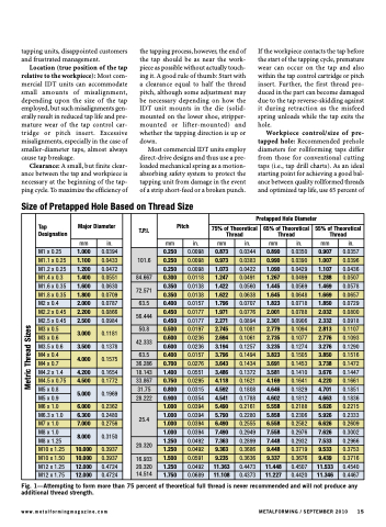
Workpiece control/size of pre- tapped hole: Recommended prehole diameters for rollforming taps differ from those for conventional cutting taps (i.e., tap drill charts). As an ideal starting point for achieving a good bal- ance between quality rollformed threads and optimized tap life, use 65 percent of
Size of Pretapped Hole Based on Thread Size
Tap Designation
Major Diameter
T.P.I.
Pitch
Pretapped Hole Diameter
75% of Theoretical Thread
65% of Theoretical Thread
55% of Theoretical Thread
mm
in.
mm
in.
mm
in.
mm
in.
mm
in.
M1 x 0.25
1.000
0.0394
101.6
0.250
0.0098
0.873
0.0344
0.890
0.0350
0.907
0.0357
M1.1 x 0.25
1.100
0.0433
0.250
0.0098
0.973
0.0383
0.990
0.0390
1.007
0.0396
M1.2 x 0.25
1.200
0.0472
0.250
0.0098
1.073
0.0422
1.090
0.0429
1.107
0.0436
M1.4 x 0.3
1.400
0.0551
84.667
0.300
0.0118
1.247
0.0491
1.267
0.0499
1.288
0.0507
M1.6 x 0.35
1.600
0.0630
72.571
0.350
0.0138
1.422
0.0560
1.445
0.0569
1.469
0.0578
M1.8 x 0.35
1.800
0.0709
0.350
0.0138
1.622
0.0638
1.645
0.0648
1.669
0.0657
M2 x 0.4
2.000
0.0787
63.5
0.400
0.0157
1.796
0.0707
1.823
0.0718
1.850
0.0729
M2.2 x 0.45
2.200
0.0866
56.444
0.450
0.0177
1.971
0.0776
2.001
0.0788
2.032
0.0800
M2.5 x 0.45
2.500
0.0984
0.450
0.0177
2.271
0.0894
2.301
0.0906
2.332
0.0918
M3 x 0.5
3.000
0.1181
50.8
0.500
0.0197
2.745
0.1081
2.779
0.1094
2.813
0.1107
M3 x 0.6
42.333
0.600
0.0236
2.694
0.1061
2.735
0.1077
2.776
0.1093
M3.5 x 0.6
3.500
0.1378
0.600
0.0236
3.194
0.1257
3.235
0.1274
3.276
0.1290
M4 x 0.4
4.000
0.1575
63.5
0.400
0.0157
3.796
0.1494
3.823
0.1505
3.850
0.1516
M4 x 0.7
36.286
0.700
0.0276
3.643
0.1434
3.691
0.1453
3.738
0.1472
M4.2 x 1.4
4.200
0.1654
18.143
1.400
0.0551
3.486
0.1372
3.581
0.1410
3.676
0.1447
M4.5 x 0.75
4.500
0.1772
33.867
0.750
0.0295
4.118
0.1621
4.169
0.1641
4.220
0.1661
M5 x 0.8
5.000
0.1969
31.75
0.800
0.0315
4.592
0.1808
4.646
0.1829
4.701
0.1851
M5 x 0.9
28.222
0.900
0.0354
4.541
0.1788
4.602
0.1812
4.663
0.1836
M6 x 1.0
6.000
0.2362
25.4
1.000
0.0394
5.490
0.2161
5.558
0.2188
5.626
0.2215
M6.3 x 1.0
6.300
0.2480
1.000
0.0394
5.790
0.2280
5.858
0.2306
5.926
0.2333
M7 x 1.0
7.000
0.2756
1.000
0.0394
6.490
0.2555
6.558
0.2582
6.626
0.2609
M8 x 1.0
8.000
0.3150
1.000
0.0394
7.490
0.2949
7.558
0.2976
7.626
0.3002
M8 x 1.25
20.320
1.250
0.0492
7.363
0.2899
7.448
0.2932
7.533
0.2966
M10 x 1.25
10.000
0.3937
1.250
0.0492
9.363
0.3686
9.448
0.3719
9.533
0.3753
M10 x 1.50
10.000
0.3937
16.933 20.320 14.514
1.500
0.0591
9.235
0.3636
9.337
0.3676
9.439
0.3716
M12 x 1.25
12.000
0.4724
1.250
0.0492
11.363
0.4473
11.448
0.4507
11.533
0.4540
M12 x 1.75
12.000
0.4724
1.750
0.0689
11.108
0.4373
11.227
0.4420
11.346
0.4467
Fig. 1—Attempting to form more than 75 percent of theoretical full thread is never recommended and will not produce any additional thread strength.
www.metalformingmagazine.com METALFORMING / SEPTEMBER 2010 15
Metric Thread Sizes
