
Page 24 - MetalForming December 2009
P. 24
Tooling Technology
Stuart Keeler (Keeler Technologies LLC) is best known worldwide for his discovery of forming limit diagrams, development of circle grid analysis and implementation of other press shop analysis tools. Stuart’s sheetmetal forming experience includes 24 years at National Steel Corporation and
12 years at The Budd Company Technical Center, enabling him to bring a very diverse background to this column and the many seminars he teaches for PMA. His most recent project is technical editor of the AHSS Application Guidelines—Version 4.1, which now is available for downloading free from www.worldautosteel.org. Keeler Technologies LLC
P.O. Box 283
Grosse Ile, MI 48138
Fax: 734/671-2271
E-mail: keeltech@comcast.net
What is the maximum allowable stretch (strain) a sheetmetal blank can withstand before failure? Pose that question to people working in the metalforming industry and a variety of answers are received. Uniform elonga- tion, total elongation and some rela- tionship to tensile strength measured from a tensile test are the most common answers. Unfortunately, stampings almost never are shaped like a tensile test specimen. Of course, others will attempt to relate maximum allowable stretch and other behaviors to the hard- ness of the material. However, the size of the crater created by a punch driven into the surface by a defined load is even less related to termination of use- ful stretchability.
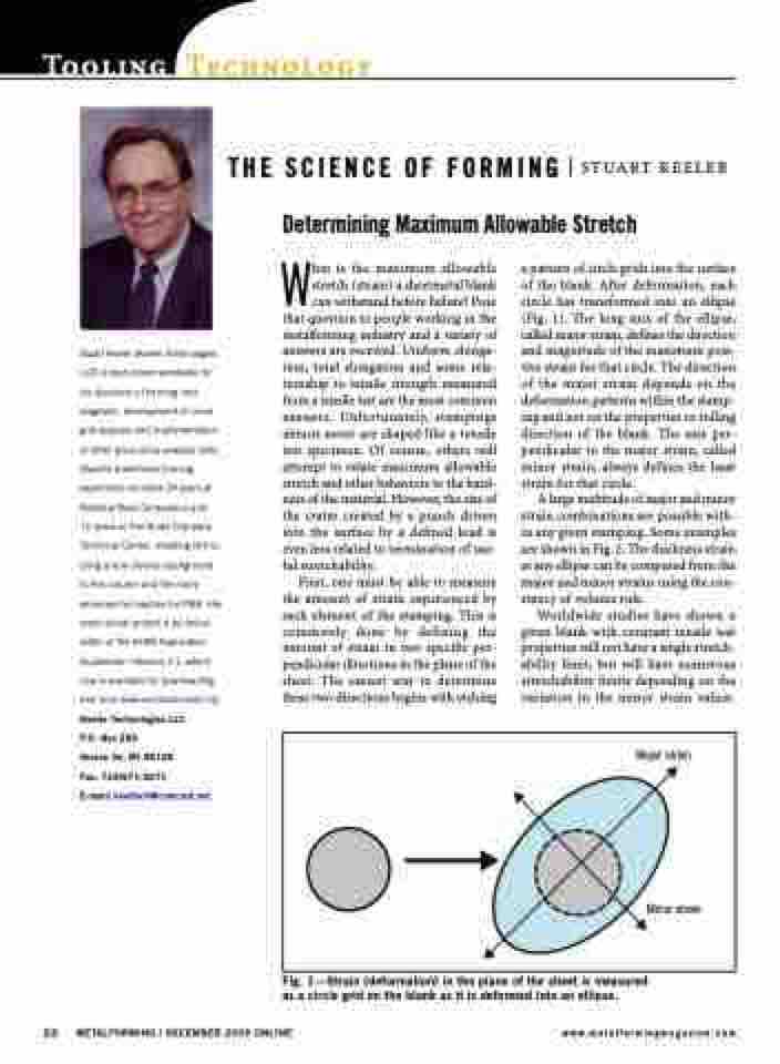
First, one must be able to measure the amount of strain experienced by each element of the stamping. This is commonly done by defining the amount of strain in two specific per- pendicular directions in the plane of the sheet. The easiest way to determine these two directions begins with etching
a pattern of circle grids into the surface of the blank. After deformation, each circle has transformed into an ellipse (Fig. 1). The long axis of the ellipse, called major strain, defines the direction and magnitude of the maximum posi- tive strain for that circle. The direction of the major strain depends on the deformation patterns within the stamp- ing and not on the properties or rolling direction of the blank. The axis per- pendicular to the major strain, called minor strain, always defines the least strain for that circle.
A large multitude of major and minor strain combinations are possible with- in any given stamping. Some examples are shown in Fig. 2. The thickness strain at any ellipse can be computed from the major and minor strains using the con- stancy of volume rule.
Worldwide studies have shown a given blank with constant tensile test properties will not have a single stretch- ability limit, but will have numerous stretchability limits depending on the variation in the minor strain values.
THE SCIENCE OF FORMING Determining Maximum Allowable Stretch
Fig. 1—Strain (deformation) in the plane of the sheet is measured as a circle grid on the blank as it is deformed into an ellipse.
22 METALFORMING / DECEMBER 2009 ONLINE www.metalformingmagazine.com
STUART KEELER
Major strain
Minor strain
