
Page 30 - MetalForming July/August 2009
P. 30
Tooling Technology
THE SCIENCE OF FORMING
What Is Yield Strength?
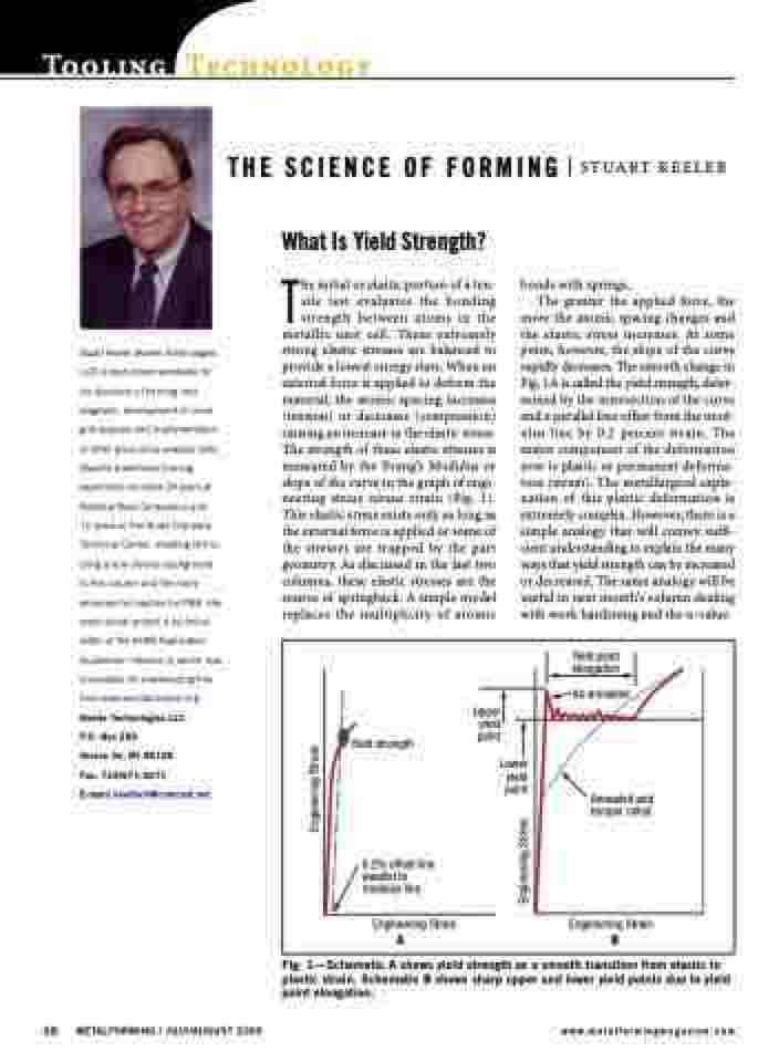
The initial or elastic portion of a ten- sile test evaluates the bonding strength between atoms in the metallic unit cell. These extremely strong elastic stresses are balanced to provide a lowest energy state. When an external force is applied to deform the material, the atomic spacing increases (tension) or decreases (compression) causing an increase in the elastic stress. The strength of these elastic stresses is measured by the Young’s Modulus or slope of the curve in the graph of engi- neering stress versus strain (Fig. 1). This elastic stress exists only as long as the external force is applied or some of the stresses are trapped by the part geometry. As discussed in the last two columns, these elastic stresses are the source of springback. A simple model replaces the multiplicity of atomic
STUART KEELER
Stuart Keeler (Keeler Technologies LLC) is best known worldwide for his discovery of forming limit diagrams, development of circle grid analysis and implementation of other press shop analysis tools. Stuart’s sheetmetal forming experience includes 24 years at National Steel Corporation and
12 years at The Budd Company Technical Center, enabling him to bring a very diverse background to this column and the many seminars he teaches for PMA. His most recent project is technical editor of the AHSS Application Guidelines—Version 4, which now is available for downloading free from www.worldautosteel.org. Keeler Technologies LLC
P.O. Box 283
Grosse Ile, MI 48138
Fax: 734/671-2271
E-mail: keeltech@comcast.net
bonds with springs.
The greater the applied force, the
more the atomic spacing changes and the elastic stress increases. At some point, however, the slope of the curve rapidly decreases. The smooth change in Fig. 1A is called the yield strength, deter- mined by the intersection of the curve and a parallel line offset from the mod- ulus line by 0.2 percent strain. The major component of the deformation now is plastic or permanent deforma- tion (strain). The metallurgical expla- nation of this plastic deformation is extremely complex. However, there is a simple analogy that will convey suffi- cient understanding to explain the many ways that yield strength can be increased or decreased. The same analogy will be useful in next month’s column dealing with work hardening and the n-value.
Yield point elongation
As-annealed
Annealed and temper rolled
Yield strength
0.2% offset line parallel to modulus line.
Engineering Strain
Upper yield point
Lower yield point
AB
Engineering Strain
28 METALFORMING / JULY/AUGUST 2009
www.metalformingmagazine.com
Fig. 1—Schematic A shows yield strength as a smooth transition from elastic to plastic strain. Schematic B shows sharp upper and lower yield points due to yield point elongation.
Engineering Stress
Engineering Stress
