
Page 34 - MetalForming July 2009
P. 34
Tooling Technology TOOLING BY DESIGN
PETER ULINTZ
Angular Piercing and Punching
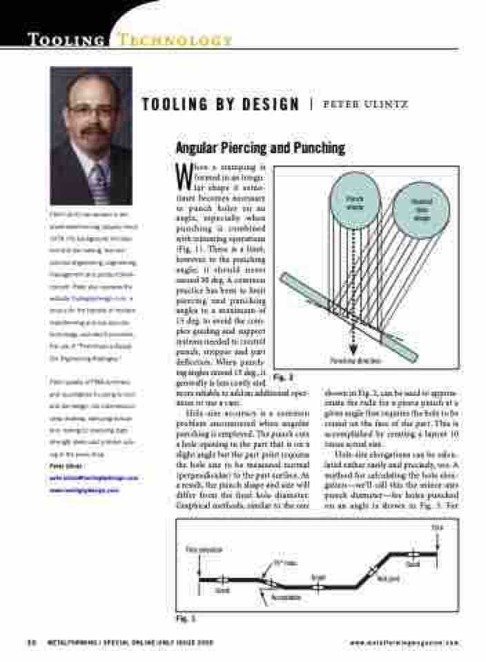
Punch shape
Desired hole shape
Punching direction
Peter Ulintz has worked in the sheetmetal-forming industry since 1978. His background includes tool and die making, tool and process engineering, engineering management and product devel- opment. Peter also operates the website ToolingbyDesign.com, a source for the transfer of modern metalforming and tool-and-die technology, and which promotes the use of “Performance-Based Die Engineering Strategies.”
Peter speaks at PMA seminars and roundtables focusing on tool and die design, die maintenance, deep drawing, stamping simula- tion, tooling for stamping high- strength steels and problem solv- ing in the press shop.
Peter Ulintz pete.ulintz@toolingbydesign.com www.toolingbydesign.com
When a stamping is
formed in an irregu-
lar shape it some-
times becomes necessary
to punch holes on an
angle, especially when
punching is combined
with trimming operations
(Fig. 1). There is a limit,
however, to the punching
angle; it should never
exceed 30 deg. A common
practice has been to limit
piercing and punching
angles to a maximum of
15 deg. to avoid the com-
plex guiding and support
systems needed to control
punch, stripper and part
deflection. When punch-
ing angles exceed 15 deg., it
generally is less costly and
more reliable to add an additional oper- ation or use a cam.
Hole-size accuracy is a common problem encountered when angular punching is employed. The punch cuts a hole opening in the part that is on a slight angle but the part print requires the hole size to be measured normal (perpendicular) to the part surface. As a result, the punch shape and size will differ from the final hole diameter. Graphical methods, similar to the one
Fig. 1
32 METALFORMING / SPECIAL ONLINE-ONLY ISSUE 2009
www.metalformingmagazine.com
Fig. 2
shown in Fig. 2, can be used to approx- imate the radii for a pierce punch at a given angle that requires the hole to be round on the face of the part. This is accomplished by creating a layout 10 times actual size.
Hole-size elongations can be calcu- lated rather easily and precisely, too. A method for calculating the hole elon- gation—we’ll call this the minor-axis punch diameter—for holes punched on an angle is shown in Fig. 3. For
Trim
Trim direction
Good
15° max.
Good
Acceptable
Good Not pref.
