
Page 35 - MetalForming May 2009
P. 35
Cutthroat competition and increas- ing part complexity drove Wright Indus- tries to adopt simulation software.
“Parts have become more complex, delivery times have tightened and we have to be price-competitive on a glob- al basis,” Veach says. “Several years ago, we decided to find a better way to design and build dies. We hired several con- sulting companies to simulate some of our more difficult dies, and concluded that Pam-Stamp was the best software for the kinds of complex dies that we build. This simulation software is easy to use; it can simulate virtually every type of operation in our business; and its predictions match the real world very closely.”
Pam-Stamp 2G covers the entire tooling process from quotation and die design through formability and tryout validation, including springback pre- diction and correction. The web- enabled technology allows the sharing of images, annotation, text and 3D mod- els, so users can make decisions online, bringing together design engineers, material providers, die designers and tryout press shops from an early stage of the design right through to produc- tion, according to ESI Group officials.
Tackles Challenging Stamping Operation
The previously described part slat- ed for the transfer-die simulation measures 30 by 36 in. with a contoured shape and multiple levels that made production difficult. Wright Industries engineers developed an initial four- station die design. The first operation features critical drawing that forms the basic contours of the part. The second operation trims away excess material, the third restrikes and forms the part to its final shape, and the fourth operation pierces and cam pierces. The combination of a deep draw and a tight material allowance makes it difficult to absorb the stretch during the drawing operation with- out exceptional thinning.
“The traditional approach for designing this type of complex die is to
shoot from the hip and hope it works,” Veach says. “We would machine the die to the part-print dimensions and mount it in the press for a trial run. It’s nearly impossible to correctly build such a dif- ficult die the first time, most often because the part wrinkles or tears in cer- tain areas. Based on the trial results, we would estimate the needed changes, take the die out of the press, make changes and hit it again. This process might be repeated several times, driving up the cost of the die and delaying the start of production.”
Addresses Thinning
and Trim-Line Placement
On this project, engineers exported the tool geometry of the initial die con- figuration from Pro/Engineer comput- er-aided-design software into the IGES file format and then imported the geometry into Pam-Stamp. The initial simulation iteration discovered areas where the die would stretch the part beyond the capabilities of the material and cause tearing. Simulation pin- pointed part-thinning areas of the part in the die, mostly centered around small radii in the initial part design. The engi- neers performed additional simulations —changing drawing depth, pressure on the binder and other variables—but
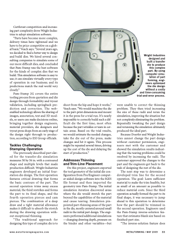
Wright Industries designed and built a transfer die to produce this complex part. By using computer simu- lation of part forming, engi- neers optimized the die design without a costly and time-consuming trial-and-error process.
were unable to correct the thinning problem. They then tried increasing the size of these radii and reran the simulation, improving the situation but not completely eliminating the problem. Repeatedly tweaking the part design and rerunning the simulation ultimately produced the ideal part.
Because Doerfer and Wright Indus- tries cannot change the part design without customer permission, engi- neers met with the customer and showed the simulation results indicat- ing that the tearing problems could be resolved by increasing the radii. The customer approved the changes to the part and the engineers got back to the task of designing the rest of the die.
The next step was to determine a developed trim line for the second operation. The goal: Leave sufficient material to make the trim feasible, but as small of an amount as possible to reduce material costs. Since the third operation actually formed the part to its final shape, it was necessary to jump ahead to this operation to determine how the part should be trimmed in the second operation. Engineers used the Pam-Stamp inverse-solution fea- ture that estimates blank size based on finished-part size.
“The inverse-solution feature does
www.metalformingmagazine.com
METALFORMING / MAY 2009 33
