
Page 34 - MetalForming May 2009
P. 34
Tooling Technology Simulation
32
METALFORMING / MAY 2009
www.metalformingmagazine.com
Computer forming simulation leads to deep-draw dies done right the first time as this Tennessee die designer and builder waves goodbye to the inefficient cut-and- hope method.
Wright Industries, acquired by Doer- fer Companies in 2004, produces automated assembly systems at its facility in Nashville, TN. It recently faced the challenge of designing a trans- fer die for a part with a deep, contoured shape. Historically, the company’s engi- neers produced an initial design based on intuition and experience, built and ran the die, and then recut and reran the die until it worked as intended. This time, engineers used Pam-Stamp 2G software from ESI Group (through ESI North America, Bloomfield Hills, MI) to simulate drawing and forming. Simu- lations identified thinning problems that the engineers corrected using a software prototype, prior to building the die, and they also used simulation to determine the trim line.
Doerfer supplies turnkey factory automation, tooling and automated- guided-vehicle technologies, and man- ufactures hydraulic presses, from 500 to
13,000 tons. Doerfer’s Wright Industries’ facility includes one of the largest tool and die facilities in the Southeast Unit- ed States, according to company offi- cials, building progressive, transfer and hand-operated line dies for customers in the agricultural, lawn products, appli- ance, automotive and HVAC industries.
Simulation Nets Quick ROI
“Using simulation instead of the conventional build-and-try method saved significant time and money on this transfer-die project,” says Bobby Veach, tool and die manager at Wright Industries. “The customer was impressed with the result, which helped to pave the path for additional work. The software allowed us to lower our quoted price on other projects, beating our competition and winning new orders. We received a return on invest- ment within three months of imple- menting the software.”
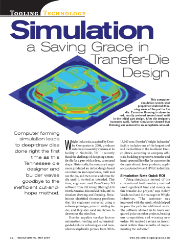
This computer- simulation screen shot pinpointed material-thin- ning areas of the part in the die. Excessive thinning is shown in red, mostly centered around small radii in the initial part design. After die designers increased radii, further simulation showed that thinning was reduced to an acceptable amount.
