
Page 42 - MetalForming December 2016
P. 42
Tooling by Design
By Peter Ulintz
Interpreting Formability Problems
Understanding the capabilities and limitations of your metal- forming-simulation software is necessary in order to accurately inter- pret and react to formability results.
Blank-prediction software relies on simplifications and assumptions in order to minimize the amount of input data and needed calculation time. These software programs provide use- ful blank-prediction results quickly, but may sacrifice accuracy for ease of use and cost-effectiveness.
One-step solutions are quick and easy to use. All they require from the user are final product geometry, usually in 3D CAD format, and minimal mate- rial properties. The software takes the final product geometry and forces it into a flat blank, providing reasonably accurate blank-shape predictions. Resultant strains from flattening the part are mapped back inversely—com- pressive strains are converted to tensile strains of equal magnitude–onto the original CAD product geometry.
Be careful when interpreting one- step results. If the solver predicts exces- sive thinning or splitting failures, that does not mean that the part being ana- lyzed could not be produced; it simply means that the part cannot be pro-
Peter Ulintz has worked in the metal stamping and tool and die industry since 1978. His back- ground includes tool and die making, tool engi- neering, process design, engineering manage- ment and advanced product development. As an educator and technical
presenter, Peter speaks at PMA national seminars, regional roundtables, international conferences, and college and university programs. He also pro- vides onsite training and consultations to the met- alforming industry.
Peter Ulintz
Technical Director, PMA pulintz@pma.org
Fig. 1—Green signifies that thinning falls within the safe zone.
duced in a single forming step. Flat-blank results from one-step solvers often are used as input data for incremental analysis. Here the process engineer conducts more complex analysis using precise blank shapes and specific material properties with production-intent tooling geometry. Because the blank profile, punch-face profile, die cavity, pressure pad and draw beads are all modeled for analysis, more accurate results are possible as
compared to a one-step solution.
A word of caution: It is not sufficient to simply achieve green results—where all thinning strains fall within the safe zone on the forming-limit diagram. As Fig. 1 illustrates, the thinning strains in the reduced diameter are located
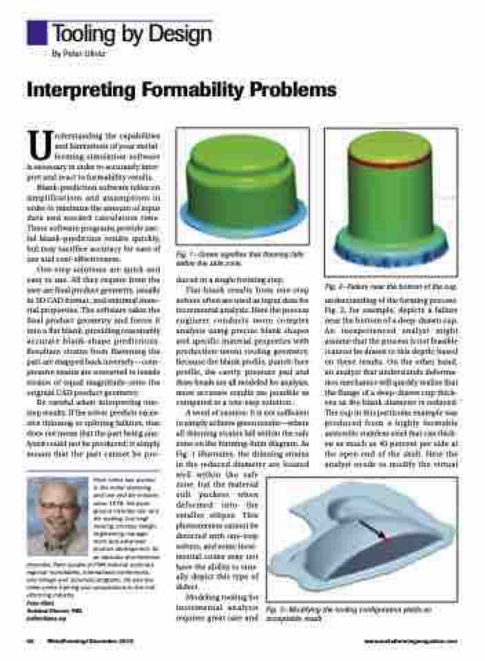
Fig. 2—Failure near the bottom of the cup.
understanding of the forming process. Fig. 2, for example, depicts a failure near the bottom of a deep-drawn cup. An inexperienced analyst might assume that the process is not feasible (cannot be drawn to this depth) based on these results. On the other hand, an analyst that understands deforma- tion mechanics will quickly realize that the flange of a deep-drawn cup thick- ens as the blank diameter is reduced. The cup in this particular example was produced from a highly formable austenitic stainless steel that can thick- en as much as 40 percent per side at the open end of the shell. Here the analyst needs to modify the virtual
well within the safe zone, but the material still puckers when deformed into the smaller ellipse. This phenomenon cannot be detected with one-step solvers, and some incre- mental codes may not have the ability to visu- ally depict this type of defect.
Modeling tooling for incremental analysis requires great care and
Fig. 3—Modifying the tooling configuration yields an acceptable result.
40 MetalForming/December 2016
www.metalformingmagazine.com
