
Page 43 - MetalForming December 2016
P. 43
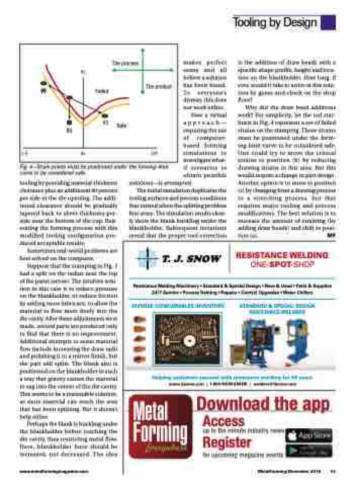
  Fig. 4—Strain points must be positioned under the forming-limit curve to be considered safe.
makes perfect sense and all believe a solution has been found. To everyone’s dismay, this does not work either.
Now a virtual approach— requiring the use of computer- based forming simulations to investigate what- if scenarios to obtain possible
is the addition of draw beads with a specific shape profile, height and loca- tion on the blankholder. How long, if ever, would it take to arrive at this solu- tion by guess-and-check on the shop floor?
Why did the draw bead additions work? For simplicity, let the red star- burst in Fig. 4 represent a set of failed strains on the stamping. Those strains must be positioned under the form- ing-limit curve to be considered safe. One could try to move the critical strains to position (b) by reducing drawing strains in this area. But this would require a change in part design. Another option is to move to position (c) by changing from a drawing process to a stretching process, but that requires major tooling and process modifications. The best solution is to increase the amount of straining (by adding draw beads) and shift to posi- tion (a). MF
RESISTANCE WELDING ONE-SPOT-SHOP
tooling by providing material-thickness clearance plus an additional 40 percent per side at the die opening. The addi- tional clearance should be gradually tapered back to sheet-thickness-per- side near the bottom of the cup. Reit- erating the forming process with this modified tooling configuration pro- duced acceptable results.
Sometimes real-world problems are best solved on the computer.
Suppose that the stamping in Fig. 3 had a split on the radius near the top of the panel (arrow). The intuitive solu- tion in this case is to reduce pressure on the blankholder, or reduce friction by adding more lubricant, to allow the material to flow more freely into the die cavity. After these adjustments were made, several parts are produced only to find that there is no improvement. Additional attempts to assist material flow include increasing the draw radii and polishing it to a mirror finish, but the part still splits. The blank also is positioned on the blankholder in such a way that gravity causes the material to sag into the center of the die cavity. This seems to be a reasonable solution, as more material can reach the area that has been splitting. But it doesn’t help either.
Perhaps the blank is buckling under the blankholder before reaching the die cavity, thus restricting metal flow. Here, blankholder force should be increased, not decreased. The idea
solutions—is attempted.
The initial simulation duplicates the
tooling surfaces and process conditions that existed when the splitting problem first arose. The simulation results clear- ly show the blank buckling under the blankholder. Subsequent iterations reveal that the proper tool correction
Tooling by Design
  (–)
e2
(a)
e1
Failed
The product
(+)
(b)
The process
(c)
Safe
                Resistance Welding Machinery • Standard & Special Design • New & Used • Parts & Supplies 24/7 Service • ProcessTraining • Repairs • Control Upgrades •Water Chillers
 DIVERSE CONSUMABLES INVENTORY
STANDARD & SPECIAL DESIGN RESISTANCE WELDERS
             Helping customers succeed with resistance welding for 50 years www.tjsnow.com | 1-800-NOW-SNOW | welders@tjsnow.com
  Download the app Access
up to the minute industry news
Register
for upcoming magazine events
           www.metalformingmagazine.com
MetalForming/December 2016 41
