
Page 14 - MetalForming December 2019
P. 14
Tooling by Design By Peter Ulintz
Redrawing Square and Rectangular Box Shells
1.20
1.00
0.80
0.60
0.40
0.20
0.00
Formability Curve
Multiple Draws
Single Draw
Rc/w = 0.067
0.10 0.20 0.30 Rc/w
Rc
w
0.00
0.40
h
At a recent seminar, as in past columns, I addressed deep drawing of square and rec- tangular box shells. Based on the resulting questions and discussions, it has become apparent that a technical column on redrawing square and rec- tangular shells might be beneficial.
Determining the Required Number of Draws
as a guide for assessing the necessary number of draw steps to produce rectangu- lar shells, based on the ratio of the wall height to the cor- ner radius (h/r). Though developed for aluminum, I find that the table also works well for steel.
The amount of reduction between redraws depends on the corner radius, which shrinks incrementally with each reduction. When two or more reductions are required, take these steps to determine the length and width of each shell:
• Starting with the fin- ished part geometry, mul-
tiply the corner radius by 3.
• Multiply using a constant of 0.75
on corner radii greater than 1/2 in., regardless of the corner size.
• Add the product for the calculation above to the current length and width,
In determining the maximum depth of a
drawn (in one operation)
square or rectangular box
shell, the size of the corner radius is the main factor, with radius of the drawn part always specified to the centerline of stock (the midpoint of material thickness).
In general, square box shells can be drawn from a flat blank to a depth equal to about 80 percent of their width with a relatively large corner radius. Rectangular box shells can be drawn to greater depths than square boxes. The depth of draw increases with the increasing width of the longest
Peter Ulintz has worked in the metal stamping and tool and die industry since 1978. His back- ground includes tool and die making, tool engi- neering, process design, engineering manage- ment and advanced product development. As an educator and technical
presenter, Peter speaks at PMA national seminars, regional roundtables, international conferences, and college and university programs. He also pro- vides onsite training and consultations to the met- alforming industry.
Peter Ulintz
Technical Director, PMA, pulintz@pma.org
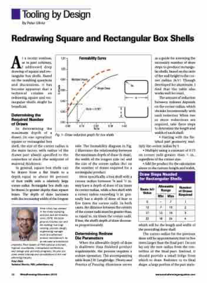
Fig. 1—Draw reduction graph for box shells
side. The formability diagram in Fig. 1 illustrates the relationship between the maximum depth of draw (h-max), the width of the longest side (w) and the size of the corner radius (Rc) on the number of draws required for a rectangular product.
More specifically, a box shell with a corner radius between 3⁄8 and 1⁄2 in. may have a depth of draw of six times its corner radius, while a box shell with a corner radius exceeding 1⁄2 in. gen- erally has a depth of draw of four to five times the corner radii. In both cases, the distance between the centers of the corner radii must be greater than, or equal to, six times the corner radii. If less, the shell’s depth of draw decreas- es proportionately.
Determining Redraw Die Parameters
When the allowable depth of draw is shallower than finished-product requirements, the process requires a redraw operation. The accompanying table from J.W. Lengbridge, Theory and Practice of Pressing Aluminum serves
which will be the length and width of the preceding draw shell.
The corner radius for the previous draw will be approximately four to five times larger than the final part. Do not lay out the new radius from the cen- terline of the final part. Instead, it should provide a small ledge from which to draw. Redrawn to its final shape, a large portion of the part mate-
Draw Steps Needed for Rectangular Shells
Basic h/r Value
Allowable Range
Number of Draws Required
Min
Max
6
—
7
1
12
7
13
2
17
13
18
3
22
18
24
4
12 MetalForming/December 2019
www.metalformingmagazine.com
h-max/w
