
Page 38 - MetalForming March 2019
P. 38
Welding Well
Multi-Variable Adaptive Control of Back of Part Exiting the Seam Welder
the control initiates a weld half-cycle impulse, it has no fur- ther influence over what happens during the weld. The actual weld heat delivered depends on what the power com- pany delivers during the half-cycle interval. The weld also is affected by the transient loading of other machinery in the factory.
Another limitation of SCR control technology: Once a weld impulse is initiated, it cannot be turned off by the con- trol. In instances when the control triggers a weld impulse just as the wheels fall off of the back edge of the part, excessive sparking and material expulsion occur because it is not possible to terminate the heat.
Inverter Controls
In order to overcome limitations imposed by SCR control technology, some manufacturers performing high-speed seam welding switch to inverter technology with expectations for superior weld current regulation, improved weld quality and increased production throughput.
Manufacturers seeking expert advice often are informed that in order to take advantage of the newer inverter tech- nology, it will be necessary to throw away the existing AC welding transformer and replace it with a newer technology mid-frequency DC welding transformer.
Wrong.
Several seam welding manufacturers that converted from single-phase AC to MFDC report decreased production throughput, reduced weld quality and increased mainte- nance. These problems worsened when the manufacturers programmed a shorter weld-impulse time and shorter cool time between each impulse in an attempt to try to meet or exceed the 120 welds/sec. impulse rate realized with the older technology control.
Examination of these welding operations reveals two fundamental causes for degraded welding performance:
• The inverter control selected, when programmed to produce short-duration impulses, delivers inaccurate and/or unstable current regulation that results in greater weld- impulse current variability than what was previously achieved with the older SCR-based control.
• During the programmed cool time between each impulse, the current decays slowly, and often doesn’t decay to zero before the next welding impulse begins. This high residual current during each cool interval, caused by the introduction of the MFDC transformer, degrades the effec- tiveness of the cool-time function. This causes the seam wheels to operate at a higher temperature to make the same sized welds than what occurred previously when the current could be brought to zero during the majority of the programmed cool interval. The elevated wheel temperature, caused from switching to an MFDC transformer, creates a number of secondary problems, which include: faster material pickup on the wheel surfaces, faster degradation of the wheel geom- etry, increased heat affected zone on the surface of the part and increased machine-maintenance requirements.
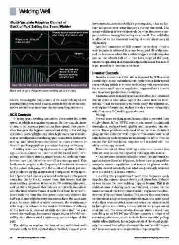
Wheel starts rolling off of back of part
Wheels bounce against each other after rolling off of back of part
Velocity
Heat automatically reduces itself and shuts off as wheel rolls off of part
Data collected and current synthesized with WeldComputer Adaptive Control
Back end of part: Adaptive seam welding at 22.5 in./sec.
wheels. Reducing the temperature of the seam welding wheels generally improves weld quality, extends the life of the elec- trodes and reduces machine-maintenance requirements.
SCR Controls
In many seam welding operations, the control limits the speed at which a machine operates. As the manufacturer attempts to increase production-line speed, the control often becomes the biggest source of variability in the welding operation, causing high scrap rates, high losses due to reduc- tion in overall production throughput, losses from destructive testing, and labor losses connected to many attempts to identify and keep problem parts from leaving the factory.
Existing seam welding operations using older technol- ogy—silicon-controlled rectifier (SCR)-based weld tech- nology controls to drive a single-phase AC welding trans- former—are limited by the control technology used. This limitation is coupled to the frequency of the power delivered by the power company, with the number of welds per sec- ond produced by the seam welder being equal to the num- ber of power half-cycles per second delivered by the power company. On 60 Hz AC power lines, this means that the seam welding operation is limited to 120 weld impulses/sec., and on 50 Hz AC power this reduces to 100 weld impulses/ sec. The time of occurrence of each weld must be synchro- nized with the time that the power company delivers the half-cycle, not with the time desired to have the weld take place. As seam-wheel velocity increases, the requirement of having to synchronize the weld with the time of delivery of the half-cycle, instead of with the time that the part enters the machine, becomes a bigger source of weld vari- ability that affects weld consistency on the edges of the part.
The ability to regulate the heat of any individual weld impulse with an SCR control also is limited, because once
36 MetalForming/March 2019
www.metalformingmagazine.com
