Main Navigation
Technologies
End Markets
News
Articles
Infocenter
Newsletters
Events
About Us
Suppliers
Advertise
Login
Subscribe
Search
Events
Newsletters
Advertise
Current Issue
Edición En Español
The official publication of
The official publication of
Close Menu
Login
|
Benefits of my account
|
Subscribe
|
Search
Login
Register
Forgot Password?
Reset Login Form
Register
Name
Contact
Employment
Password
Technologies
Additive Manufacturing
Bending
CNC Punching
Coil and Sheet Handling
Cutting
Finishing
In-Die Operations
Lubrication
Management
Materials
Other Processes
Pressroom Automation
Quality Control
Safety
Sensing/Electronics/IOT
Software
Stamping Presses
Tooling
Training
Welding and Joining
End Markets
Aerospace
Agriculture
Appliance
Automotive
Electronics
Hardware
Industrial
Job Shop
Marine
Medical
Military
Other
News
Articles
Current Issue
Archive
Featured Articles
Authors
Love Letters
5 Questions
Glossary
Metalforming Español
Stamping Journal
Infocenter
Tool & Die ebook
Podcasts
Videos
Webinars
White Papers
Newsletters
MetalForming
Business Edge
MetalForming Automotive
MetalForming Espanol
Events
Fabrication Strategy Summit
Hot Stamping Experience
Industry 4.0/ERP
Metal Stamping Technology
Mexico Stamping Technology
FABTECH
FABTECH Previews
Four on the Floor
Seen at FABTECH
About Us
Contact Us
Job Center
Sitemap
Subscribe
Terms and Conditions
Suppliers
Advertise
Print
Digital
Video
Social Media
Events
Editorial Guidelines
Home
❯
technology
Select Type of Technology
All Technology
Additive Manufacturing
Bending
CNC Punching
Coil and Sheet Handling
Cutting
Finishing
In-Die Operations
Lubrication
Management
Materials
Other Processes
Pressroom Automation
Quality Control
Safety
Sensing/Electronics/IOT
Software
Stamping Presses
Tooling
Training
Welding and Joining
Select Type of Content
All Content
Articles (10858)
News (4059)
Commentary (996)
Products (3984)
Videos (204)
Podcasts (130)
White Papers (39)
Events (6)
Webinars (130)
Management
Metalworking-Machinery Orders on the Upswing
January 14, 2026
Management
ECI Software Solutions Names Graham Younger Chief Revenue Officer
January 14, 2026
Management
2026 Metal Forming & Fabricating Industry Trends
Steve Bieszczat
January 13, 2026
Quality Control
Bridge-Type CMMs for Large-Scale Heavy-Duty Measurement
January 13, 2026
CNC Punching
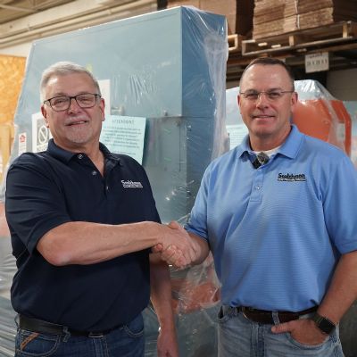
Sales-Leadership Transition at Scotchman Industrie...
January 13, 2026
Sensing/Electronics/IOT
Wintriss Controls Group Acquires ISB
January 13, 2026
Cutting
Laserdyne Appoints Fabrizio Anzalone Chief Executive Officer
January 12, 2026
Stamping Presses
Seyi Adds Regional Sales Manager for West Coast
January 12, 2026
Pressroom Automation
Marion Die & Fixture Sponsors Robotics Team
January 8, 2026
Pressroom Automation
Mayfran Expanding in Ohio
January 8, 2026
Management
Cincinnati Inc. Recognized for its Support of Vete...
January 7, 2026
Management
U.S. Auto Sales Close 2025 with Lack of Momentum
January 7, 2026
Management
Beyond Survival: How You Can Win in 2026
Mike Devereux
January 6, 2026
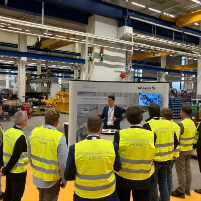
Cutting
Laser Blanking Line Stars at Andritz Schuler Technology...
December 30, 2025
Management
Leadership Transition at Scandic Springs
December 30, 2025
Management
MetalForming Minute: December 2025
December 29, 2025
VIDEO
More
Subscribe to the Newsletter
Start receiving newsletters.


 VIDEO
VIDEO