
Page 38 - MetalForming-Dec-2018-issue
P. 38
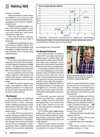
   Force vs. Amps (Tip Force 490 lb.)
20 18 16 14 12 10
8 6 4 2 0
Sample Data Lower Amp Limit   Lower Pull-Force Limit   Expulsion Limit   Ideal Amp Setting
   Expulsion
            No Nugget
Nugget
  0 2 4 6 8 10 12 14 Amps (kA)
   Welding Well
pressure is reached.
• Electronic pressure control. Allows
the weld force to be set from the weld control, thereby eliminating the man- ual regulator that operators could pre- viously access.
• Weld log (see Weld Log table). Cre- ates a date and time stamp for every weld sequence, including key param- eters such as weld time, weld current and pressure/weld force.
• Error log. Generates a date and time stamp each time that a fault is generated.
In addition to purchasing the new, state-of-the-art welder control, HTT also invested in onsite installation and training by a certified resistance-weld- ing technician who set up the initial weld schedules.
Extra Effort
At this point, Sonnenberg and his associates at HTT put in the extra effort to ensure long-term resistance-welding success. He educated himself on the resistance-welding process and learned how to use all aspects of the control.
Also, he performed a process study using a consistent weld pressure and various weld currents to find the opti- mum current setting (see Force vs. Amps graph).
In addition, machine operators no longer were allowed to adjust weld- schedule parameters. To compensate for tip wear, they could only select pre- set proven weld schedules.
The Reward
After installing the new control and performing the process study, HTT finally started to obtain consistent results, enabling Sonnenberg to review data from the weld log for any varia- tions in the process that might cause quality issues.
As a result, HTT was authorized to stop the 100-percent quality check pre- viously required by its customer, which saved around $30,000/yr. In addition, the company now uses around $2000 less per year in consumables (copper electrodes). These combined savings paid for the new control, installation
Graph shows the results of a process study using a consistent weld pressure and vari- ous weld currents to find the optimum current setting.
 36 MetalForming/December 2018
www.metalformingmagazine.com
and training in just a few months.
The Reward Continues
After several months of consistent results, HTT once again experienced quality issues. An outside expert sug- gested that if the weld current and pres- sure value were consistent, as was proven by the new control, the problem likely was an electrode or part fitup issue.
Sonnenberg confirmed that oper- ators were changing tips at the proper intervals. Then he looked at the parts and noticed that some were out of round. An internal discussion revealed that operators routinely turned up the weld force when they saw such parts. Recognizing that using the welder as a forming machine to overcome part springback was a bad idea, Sonnen- berg had new parts made, and spot- weld quality immediately returned to normal.
A third-shift operator reported another potential issue, a popping noise coming from the weld area, accompanied by a low-current error on the control. However, by the time the first shift arrived, everything was back to normal.
HTT’s outside expert suggested that another part or fitup issue was at the root of the problem, and that if it hap- pened again, production should be stopped until Sonnenberg could come to the machine.
When the same scenario occurred several weeks later, Sonnenberg found oil absorbent on some of the parts,
Miles Sonnenberg of HTT, Inc. took the guesswork out of arriving at solutions to resistance-welding quality issues.
which he suspected had been picked up from the bottom of the parts con- tainer. Through a controlled experi- ment with oil absorbent applied to the part manually, he was able to recreate the condition.
Process knowledge and modern electronics saved the day again and serve to illustrate why the resistance- welding process should be treated as a science instead of a black art. MF
Editor’s note: The author thanks the following for their significant contri- butions to this article:
• Miles Sonnenberg, manufacturing engineer, HTT, Inc.
• John Hill, regional (WI and MN) sales manager, T. J. Snow
• Josh Garmon, service manager, T. J. Snow
• Paul Bush, certified resistance welding technician, T. J. Snow.
Tip Force (lb. · ft.)
