
Page 50 - MetalForming-Mar-2018-issue
P. 50
Die-Design and Simulation
of a blanked component. Designers also can define the face constraint in X or Y directions, or in both, particularly useful when looking to blank only specific areas of a model for step-by-step stage unfolding. In addition, the process of managing strip layouts using double-component geometry has been enhanced, thus reducing development time of a 3D strip design.
CAM developments include faster geometry preparation as well as an enhanced 2.5-axis chamfering strategy that provides many updates, including intelligent approach and retract points, advanced obstacle management, and speed improvement.
User-interface improvements to the CAM navigator enable showing of build-process status on the operation itself, allowing the process manager to be switched off if required. Tool-sheet reports have been updated, allowing users to benefit from enhancements to the software’s snapshot man- ager. In addition, for users requiring hole information gen- erated from the feature recognition, the data can be exported to CSV files for external use.
Also, for improved quality control, a new VISI-to-PC- DMIS interface enables PC-DMIS to read native VISI CAD files directly, with annotations and points previously defined in VISI loaded automatically into PC-DMIS.
TST Tooling Software Technology, LLC: www.tst-software.com
Feasibility Early in Development Cycle
Software: AutoForm-StampingAdviserplus
When applied from early on in the part-design cycle, AutoForm-StampingAdviserplus from AutoForm Engineering USA can deliver significant benefits in terms of robust part manufacturability and material cost stability, according to company officials.
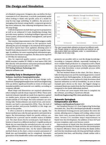
Blank shape and dimensions are required submissions when stampers and die shops respond to RFQs. These early material estimates typically are made from experience gained on similar parts, process and equipment constraints, or simple unfolds of a 3D shape. But early estimates can carry strong risks. Underestimates can result in loss, and overes- timates can lead to uncompetitive RFQs. Thus, the lack of accurate product and process feasibility at this stage can wipe out any profits.
It often is desired to determine blank size rapidly. The fastest method uses only the part geometry and material as inputs. But determining a blank size quickly without con- sideration for a process can be another source of hidden cost. The chart shows this for several parts. Each blank uti- lization is based on a different method. A rapidly produced blank size not matching the intended process can result in a large difference in blank size and, therefore, higher costs.
With little additional time, via the Quick Addendum method shown in the chart, a more accurate assessment of blank size and formability can be completed. Automatic generation of the blankholder surface and simple addendum
This chart reveals blank utilization produced via different meth- ods. Though relying on only part geometry and material can rap- idly produce blank-size estimates, under- or overestimates at this stage can be very costly.
geometry are possible with no real die-design knowledge, according to company officials, reportedly resulting in a more reliable blank prediction in comparison with a blank size based solely on part geometry. Further adjustments by the user help determine a more probable process while helping reduce blank size.
The last method shown in the chart, Die Face, shows a fully developed process and the matching geometry created using AutoForm-DieDesignerplus. At this point, additional process conditions can be explored to help determine ideal material utilization as well as formability. As seen in these example parts shown on the chart, the biggest change in estimated blank size results from the Part Geometry method compared to the Quick Addendum method.
All of these use cases require little time to complete via the software, according to AutoForm officials.
AutoForm Engineering USA: www.autoform.com
Automatic Springback Compensation and More Software: eta/Dynaform Version 5.9.3
eta/Dynaform Version 5.9.3, from Engineering Technology Associates, Inc., Troy, MI, is developed specifically to simulate the sheetmetal-forming process and analyze the entire die system, allowing users to bypass soft tooling, reduce tryout time, lower costs, increase productivity and improve cycle times. Version 5.9.3 includes major improvements in blank/trim-line development, the addition of Auto SCP and process templates, and a new license control.
Improvements in blank/trim-line development include combining the interface for blank and trim-line development to improve efficiency. Users can develop the blank outline and trim line simultaneously, develop partial blank outlines and partial trim lines, and develop a blank outline with a cut pattern.
48 MetalForming/March 2018
www.metalformingmagazine.com
