
Page 47 - MetalForming-Feb-2018-issue
P. 47
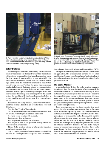
  Blanked area
  B—Here’s another case where a stamper has installed light cur- tains without considering scrap egress. Large areas of the cur- tains have been blanked to allow positioning of the scrap bin and for scrap to exit the press, compromising safety.
Safety Distance
With the light curtain and press having control-reliable controls, the stamper can then safely predict that the machine will receive a command to stop hazardous motion when the light curtain detects an object in its sensing field. It is important to understand, though, that the controls for the light curtain and the press both take time to react to the object being sensed. Further, the press has numerous mechanical elements that must actuate in response to the stop command and overcome the inertia of the moving ram. Therefore, during light-curtain setup, stampers must take care to locate the sensing field far enough from the hazard so that the machine will stop hazardous motion before a person reaching through the sensing field can reach the hazard.
To calculate this safety distance, industry experts devel- oped this formula based on an operator hand speed of 63 in./sec.:
Ds=Kx(Ts+Tc+Tr+Tbm)+D(pf)
Ds = Minimum safety distance between the device and the nearest point of operation hazard (in inches)
K = Hand-speed constant (63 in./sec.)\
Ts = Stopping time of the press
Tc = Response time of the control system
Tr = Response time of the presence-sensing device (as
stated by the manufacturer)
Tbm = Brake-monitor setting, a value greater than the
actual usual stopping time
D(pf ) = Depth-penetration factor—this refers to the added
distance the sensing field will be placed from the hazard,
C—In this case, the stamper has set the hairpin guards wide open to allow the largest parts to escape. Once set in this location, they were never returned to a narrower opening. The resulting guarding scheme does not comply with the OSHA standard for barrier guards—an operator easily can reach through the window.
depending on the curtain’s minimum object sensitivity (MOS). Stampers must thoroughly understand this formula and its application. The most common mistakes we see when applying the formula come from a lack of understanding of the brake-monitor setting, and the application of the depth-
penetration factor.
The Brake Monitor
A control-reliable device, the brake monitor measures the elapsed time from the initiation of the stop until the eventual actual halting of ram motion. With nearly all solid- state controls, when the press stops the monitor measures the elapsed time and compares it to a maximum allowable value preset by the press manufacturer. If the time exceeds the monitor’s maximum value, the unit produces a fault that prevents the press from being stroking without an oper- ator first resetting the fault.
Press manufacturers set the brake monitor to a point greater than the actual average stopping time of the press. Thus, as the brake gradually wears the machine does not instantly fault and render the press unusable until the stam- per adjusts or replaces the brake. Instead, this built-in allowance enables most presses to operate for several years before reaching the limit. With regular checks by mainte- nance, the brake’s gradually degraded performance should be detected well before it reaches the limit and a stamper should never experience unplanned downtime due to brake wear. Should the brake wear before maintenance is per- formed, the measured stopping time will exceed the limit and a brake-monitor fault will be initiated.
www.metalformingmagazine.com
MetalForming/February 2018 45
