
Page 84 - MetalForming July 2017
P. 84
Custom Spring Design from A to Z
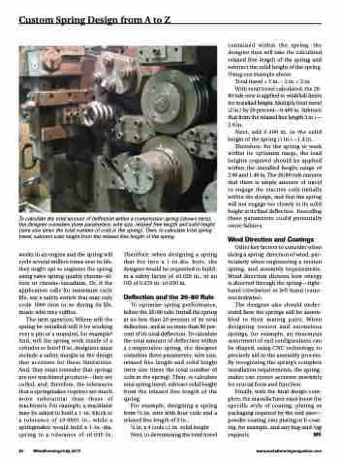
To calculate the total amount of deflection within a compression spring (shown here), the designer considers three parameters: wire size, relaxed free length and solid height (wire size times the total number of coils in the spring). Then, to calculate total spring travel, subtract solid height from the relaxed free length of the spring.
contained within the spring, the designer then will take the calculated relaxed free length of the spring and subtract the solid height of the spring. Using our example above:
Totaltravel=3in.–1in.=2in.
With total travel calculated, the 20- 80 rule now is applied to establish limits for installed height. Multiply total travel (2 in.) by 20 percent—0.400 in. Subtract that from the relaxed free length 3 in.)— 2.6 in.
Next, add 0.400 in. to the solid height of the spring (1 in.)—1.4 in.
Therefore, for the spring to work within its optimum range, the load heights required should be applied within the installed height range of 2.60 and 1.40 in. The 20/80 rule ensures that there is ample amount of travel to engage the inactive coils initially within the design, and that the spring will not engage too closely to its solid height at its final deflection. Exceeding these parameters could potentially cause failures.
Wind Direction and Coatings
Other key factors to consider when sizing a spring: direction of wind, par- ticularly when engineering a torsion spring, and assembly requirements. Wind direction dictates how energy is directed through the spring—right- hand (clockwise) or left-hand (coun- terclockwise).
The designer also should under- stand how the springs will be assem- bled to their mating parts. When designing torsion and extensions springs, for example, an enormous assortment of end configurations can be shaped, using CNC technology, to precisely aid in the assembly process. By recognizing the spring’s complete installation requirements, the spring- maker can ensure accurate assembly for crucial form and function.
Finally, with the final design com- plete, the manufacturer must know the specific style of coating, plating or packaging required by the end user— powder coating, zinc plating or E-coat- ing, for example, and any bag-and-tag requests. MF
works in an engine and the spring will cycle several million times over its life, they might opt to engineer the spring using valve-spring-quality chrome-sil- icon or chrome-vanadium. Or, if the application calls for minimum cycle life, say a safety switch that may only cycle 1000 time or so during its life, music wire may suffice.
The next question: Where will the spring be installed/will it be working over a pin or a mandrel, for example? And, will the spring work inside of a cylinder or bore? If so, designers must include a safety margin in the design that accounts for these limitations. And, they must consider that springs are not machined products—they are coiled, and, therefore, the tolerances that a springmaker requires are much more substantial than those of machinists. For example, a machinist may be asked to hold a 1-in. block to a tolerance of ±0.0001 in., while a springmaker would hold a 1-in.-dia. spring to a tolerance of ±0.030 in.
Therefore, when designing a spring that fits into a 1-in.dia. bore, the designer would be requested to build- in a safety factor of ±0.030 in., or an OD of 0.970 in. ±0.030 in.
Deflection and the 20-80 Rule
To optimize spring performance, follow the 20/80 rule: Install the spring at no less than 20 percent of its total deflection, and at no more than 80 per- cent of its total deflection. To calculate the total amount of deflection within a compression spring, the designer considers three parameters: wire size, relaxed free length and solid height (wire size times the total number of coils in the spring). Then, to calculate total spring travel, subtract solid height from the relaxed free length of the spring.
For example, designing a spring from 1⁄4-in. wire with four coils and a relaxed free length of 3 in.:
1⁄4 in. x 4 coils =1 in. solid height Next, in determining the total travel
82 MetalForming/July 2017
www.metalformingmagazine.com
