
Page 50 - MetalForming April 2017
P. 50
The Science of Forming
By Stuart Keeler
Don’t Assume Yesterday’s Corrective Actions Will Work Today
Metalformers occasionally try to apply press-shop practices that have worked in the past when attempt- ing to solve current metalforming challenges.
Does this sound familiar?
“I experienced this same problem 22 years ago with a part almost identical to this one. I simply made an adjustment to the tool; I can make the same change to this tool.”
Such thinking creates some major issues:
1) Were the 60 or more system inputs measured and recorded from the old part?
2) Do these inputs exactly match the same inputs of the current part?
3) If not, why would making the same adjustment 22 years later correct the current problem?
Consider these enhancements to steel properties that require a new approach to press-shop problem-solving.
Stretching
At the start of deformation, some parts form a narrow zone of stretch that can range from a tube to an edge con- traction. This happens mostly for lower values of n-value found in some high-strength low-alloy steels. The higher the strength, the lower the n-value. Newer dual-phase steels from the advanced-high-strength-steel (AHSS) group have especially high n-values in the strain range of 2 to 5 percent that help to reduce peak strains.
Element Blankholder bend
AB
Element straightened
No strain in the axial direction
Punch
RD
Fig. 1—Bend axis parallel to rolling direction increases cracking potential because tensile stress is across the long inclusion.
Bending
Early steel had sulfur-based inclusions (primarily man- ganese-sulfur) that ran parallel to the coil-rolling direction (Fig. 1). If a blank was formed by bending parallel to the inclusion, a crack or even a through-thickness split would occur at the inclusion. To avoid these cracks, blanks were formed by turning them 90 deg. Today, the amount of sulfur has been greatly reduced in most steels and the inclusions have disappeared. This allows multidirectional steel align- ment and bending.
Stuart Keeler (Keeler Technologies LLC) is known worldwide for his discovery of forming limit diagrams, development of circle-grid analysis and implementa- tion of other press-shop analysis tools. Keeler’s metal- forming experience includes 24 years at National Steel Corporation and 12 years at The Budd Compa- ny Technical Center, enabling him to bring a very diverse background to this column and to the semi- nars he teaches for PMA.
Keeler Technologies LLC
P.O. Box 283 | Grosse Ile, MI 48138 keeltech@comcast.net
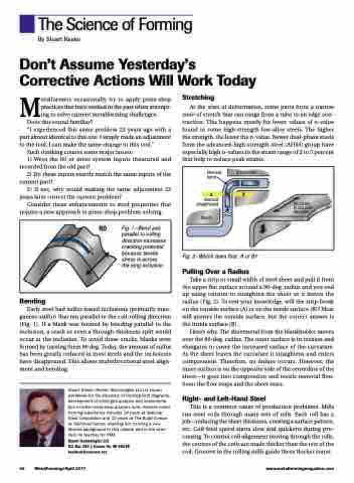
Fig. 2—Which tears first: A or B?
Pulling Over a Radius
Take a strip or small width of steel sheet and pull it from the upper flat surface around a 90-deg. radius and you end up using tension to straighten the sheet as it leaves the radius (Fig. 2). To test your knowledge, will the strip break on the outside surface (A) or on the inside surface (B)? Most will answer the outside surface, but the correct answer is the inside surface (B).
Here’s why. The sheetmetal from the blankholder moves over the 90-deg. radius. The outer surface is in tension and elongates to cover the increased surface of the curvature. As the sheet leaves the curvature it straightens and enters compression. Therefore, no failure occurs. However, the inner surface is on the opposite side of the centerline of the sheet—it goes into compression and resists material flow. Soon the flow stops and the sheet tears.
Right- and Left-Hand Steel
This is a common cause of production problems. Mills run steel coils through many sets of rolls. Each roll has a job—reducing the sheet thickness, creating a surface pattern, etc. Coil-feed speed starts slow and quickens during pro- cessing. To control coil alignment moving through the rolls, the centers of the coils are made thicker than the rest of the coil. Grooves in the rolling mills guide these thicker zones.
48 MetalForming/April 2017
www.metalformingmagazine.com
