
Page 24 - MetalForming April 2017
P. 24
In-Die Micro Pin
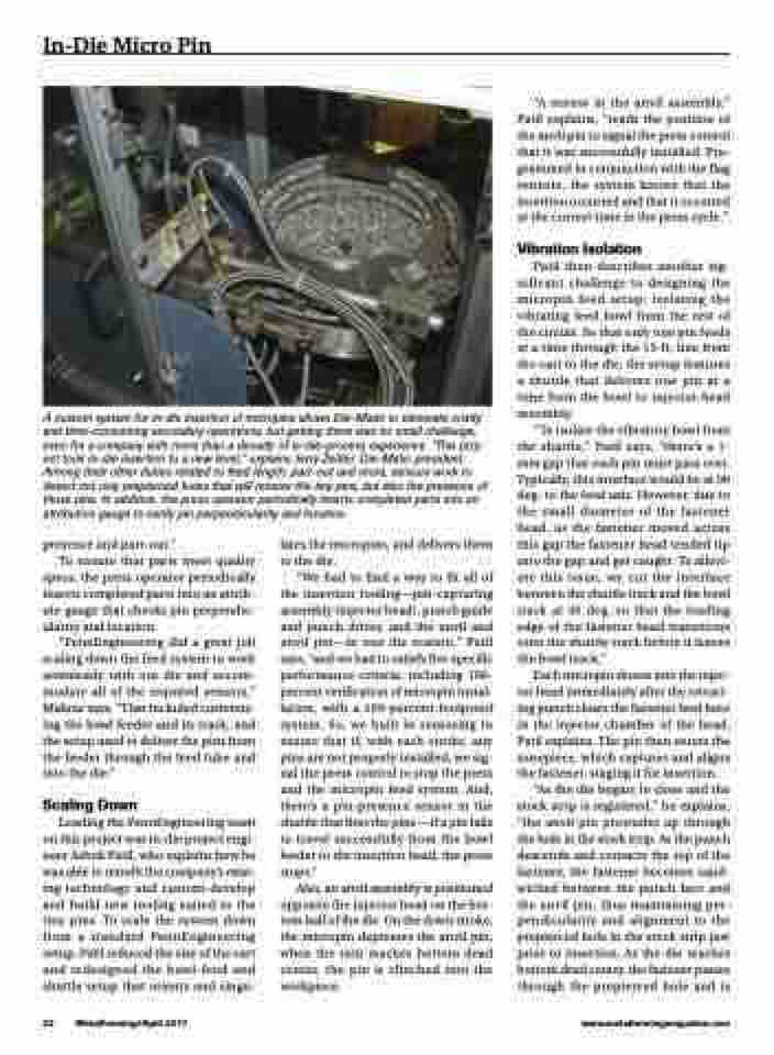
A custom system for in-die insertion of micropins allows Die-Matic to eliminate costly and time-consuming secondary operations, but getting there was no small challenge, even for a company with more than a decade of in-die-process experience. “This proj- ect took in-die insertion to a new level,” explains Jerry Zeitler, Die-Matic president. Among their other duties related to feed length, part-out and more, sensors work to detect not only prepierced holes that will receive the tiny pins, but also the presence of those pins. In addition, the press operator periodically inserts completed parts into an attribution gauge to verify pin perpendicularity and location.
“A sensor in the anvil assembly,” Patil explains, “reads the position of the anvil pin to signal the press control that it was successfully installed. Pro- grammed in conjunction with the flag sensors, the system knows that the insertion occurred and that it occurred at the correct time in the press cycle.”
Vibration Isolation
Patil then describes another sig- nificant challenge to designing the micropin feed setup: isolating the vibrating feed bowl from the rest of the circuit. So that only one pin feeds at a time through the 15-ft. line from the cart to the die, the setup features a shuttle that delivers one pin at a time from the bowl to injector-head assembly.
“To isolate the vibratory bowl from the shuttle,” Patil says, “there’s a 1- mm gap that each pin must pass over. Typically, this interface would be at 90 deg. to the feed axis. However, due to the small diameter of the fastener head, as the fastener moved across this gap the fastener head tended tip into the gap and get caught. To allevi- ate this issue, we cut the interface between the shuttle track and the bowl track at 45 deg. so that the leading edge of the fastener head transitions onto the shuttle track before it leaves the bowl track.”
Each micropin shoots into the injec- tor head immediately after the retract- ing punch clears the fastener feed bore in the injector chamber of the head, Patil explains. The pin then enters the nosepiece, which captures and aligns the fastener, staging it for insertion.
“As the die begins to close and the stock strip is registered,” he explains, “the anvil pin protrudes up through the hole in the stock strip. As the punch descends and contacts the top of the fastener, the fastener becomes sand- wiched between the punch face and the anvil pin, thus maintaining per- pendicularity and alignment to the prepierced hole in the stock strip just prior to insertion. As the die reaches bottom dead center, the fastener passes through the prepierced hole and is
presence and part-out.”
To ensure that parts meet quality
specs, the press operator periodically inserts completed parts into an attrib- ute gauge that checks pin perpendic- ularity and location.
“PennEngineering did a great job scaling down the feed system to work seamlessly with our die and accom- modate all of the required sensors,” Mahnic says. “That included customiz- ing the bowl feeder and its track, and the setup used to deliver the pins from the feeder through the feed tube and into the die.”
Scaling Down
Leading the PennEngineering team on this project was in-die project engi- neer Ashok Patil, who explains how he was able to retrofit the company’s exist- ing technology and custom-develop and build new tooling suited to the tiny pins. To scale the system down from a standard PennEngineering setup, Patil reduced the size of the cart and redesigned the bowl-feed and shuttle setup that orients and singu-
lates the micropins, and delivers them to the die.
“Wehadtofindawaytofitallof the insertion tooling—pin-capturing assembly (injector head), punch guide and punch driver, and the anvil and anvil pin—in one die station,” Patil says, “and we had to satisfy five specific performance criteria, including 100- percent verification of micropin instal- lation, with a 100-percent foolproof system. So, we built in sensoring to ensure that if, with each stroke, any pins are not properly installed, we sig- nal the press control to stop the press and the micropin feed system. And, there’s a pin-presence sensor in the shuttle that fires the pins —if a pin fails to travel successfully from the bowl feeder to the insertion head, the press stops.”
Also, an anvil assembly is positioned opposite the injector head on the bot- tom half of the die. On the down stroke, the micropin depresses the anvil pin; when the ram reaches bottom dead center, the pin is clinched into the workpiece.
22 MetalForming/April 2017
www.metalformingmagazine.com
